Pass Transistor Logic (PTL) is one of the most important digital logic design techniques used in modern CMOS and VLSI (Very Large Scale Integration) systems. Unlike conventional CMOS logic, which uses complementary pull-up and pull-down transistor networks, Pass Transistor Logic uses transistors primarily as switches that transfer logic signals from one point to another.
At first glance, PTL may appear complicated because it involves MOSFET transistors and semiconductor concepts. However, the basic idea is surprisingly simple. Imagine a water pipe controlled by a valve. When the valve is open, water flows through the pipe. When the valve is closed, the flow stops. A pass transistor behaves in a similar way—it acts like an electronic switch that either allows or blocks the flow of electrical signals.
Because PTL uses fewer transistors than conventional CMOS logic, it offers several advantages, including lower power consumption, reduced chip area, faster switching speed, and lower manufacturing cost. These characteristics make it highly valuable in integrated circuits such as multiplexers, arithmetic circuits, memory systems, processors, and portable electronic devices.
This article explains Pass Transistor Logic in a simple and structured manner suitable for Class 12 students, undergraduate engineering students, competitive examination aspirants, and beginners in VLSI design. By the end of this guide, you will understand how PTL works, why it is used, where it is applied, and what its limitations are.
What is Pass Transistor Logic?
Pass Transistor Logic (PTL) is a digital circuit design technique in which MOS transistors are used as switches to pass logic signals directly between circuit nodes. Instead of creating separate pull-up and pull-down networks as in CMOS logic, PTL transfers input signals through controlled transistors to produce the desired output.
In simple words, A transistor in PTL acts more like an electronic switch than an amplifier.
- When the switch is ON, the signal reaches the output.
- When the switch is OFF, the signal is blocked.
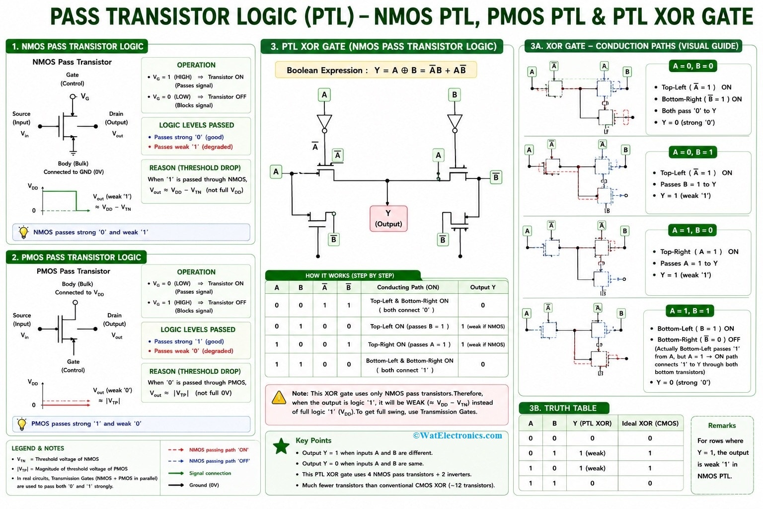
Pass Transistor Logic (PTL)
Simple Analogy
Imagine a classroom door.
- Door Open → Students can enter.
- Door Closed → Students cannot enter.
Similarly,
- Transistor ON → Signal passes.
- Transistor OFF → Signal does not pass.
This simple switching action forms the basis of Pass Transistor Logic.
Basic Principle of Pass Transistor Logic
The working principle of PTL depends on MOSFETs operating as controlled switches.
The transistor has three important terminals:
- Gate (Control terminal)
- Source
- Drain
The voltage applied at the gate determines whether the transistor conducts.
When Gate Voltage is HIGH
- The transistor turns ON.
- Input signal passes to output.
When Gate Voltage is LOW
- The transistor turns OFF.
- Signal cannot reach the output.
Conceptual Diagram
Control Signal
│
▼
┌─────┐
Input ───────►MOSFET├────────► Output
└─────┘
- When the MOSFET is ON, the input is connected to the output.
- When OFF, both terminals become isolated.
Why is Pass Transistor Logic Needed?
Conventional CMOS circuits are reliable but often require many transistors.
For example,
- CMOS XOR Gate → about 12 transistors
- PTL XOR Gate → as few as 6 transistors
Using fewer transistors provides many advantages:
- Smaller chip size.
- Lower manufacturing cost.
- Lower power consumption.
- Faster operation.
- Reduced wiring complexity.
NMOS as a Pass Transistor
An NMOS transistor is very good at passing a logic LOW (0).
However, it has difficulty passing a perfect logic HIGH (1).
Suppose, Supply Voltage = 5V
Input = 5V
The output becomes approximately
5V − Threshold Voltage
If threshold voltage = 0.7V
Output ≈ 4.3V
instead of 5V.
This is known as Threshold Voltage Loss
PMOS as a Pass Transistor
PMOS behaves opposite to NMOS.
It passes
- Strong Logic 1
- Weak Logic 0
Therefore,
NMOS and PMOS have complementary characteristics.
Comparison
|
Feature |
NMOS | PMOS |
|
Passes Logic 0 |
Excellent | Weak |
|
Passes Logic 1 |
Weak |
Excellent |
| Electron Mobility | High |
Lower |
| Speed | Faster |
Slower |
Threshold Voltage Problem
The biggest limitation of a single-pass transistor is threshold voltage drop.
For NMOS,
Output HIGH = VDD − VT
This reduced voltage is called a Weak Logic High.
Similarly,
PMOS produces a weak logic LOW.
This problem limits the use of individual pass transistors in complex circuits.
Solution: Transmission Gate
To eliminate threshold voltage loss,
Engineers combine
- One NMOS
- One PMOS
connected in parallel.
This combination is called a Transmission Gate.
- The NMOS passes strong LOW.
- The PMOS passes strong HIGH.
Together they provide nearly ideal switching.
Working of Pass Transistor Logic
The operation of PTL consists of four basic steps.
- Step 1: Input signal arrives.
- Step 2: Control signal determines whether the transistor turns ON.
- Step 3: If ON, signal passes to output.
- Step 4: If OFF, output remains disconnected.
Logic Gates Using Pass Transistor Logic
PTL can implement almost every digital logic gate.
These include
- NOT
- AND
- OR
- XOR
- XNOR
- Multiplexer
Among these, the XOR gate benefits the most because PTL significantly reduces transistor count.
PTL XOR Gate
One of the biggest advantages of PTL is efficient XOR implementation.
Traditional CMOS ≈12 transistors
PTL ≈6 transistors
Benefits
- Smaller area
- Faster operation
- Lower power
Multiplexer using Pass Transistor Logic
A multiplexer selects one input from multiple inputs. PTL implements multiplexers very efficiently because transistors naturally behave like switches. Conceptually,
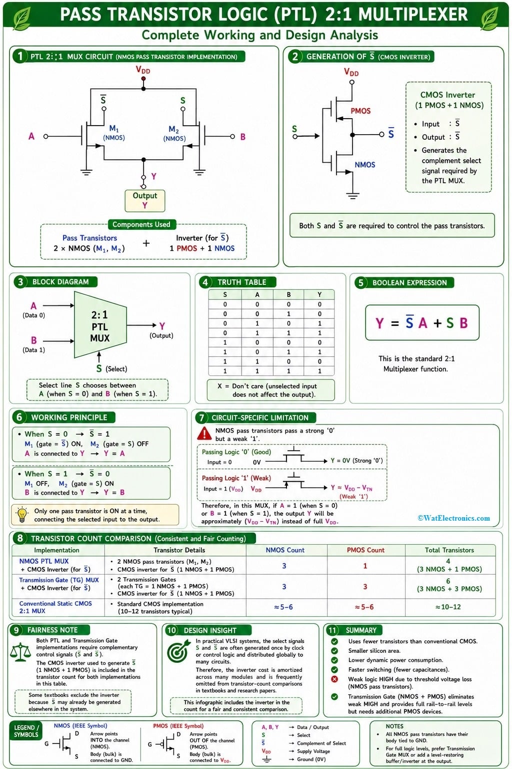
Pass Transistor Logic (PTL) as a Multiplexer
Advantages of Pass Transistor Logic
1. Fewer Transistors
PTL requires fewer transistors than CMOS.
Benefits include
- Lower area
- Lower fabrication cost
2. Lower Power Consumption
Smaller transistor count reduces
- Dynamic power
- Switching losses
This makes PTL suitable for battery-operated devices.
3. Faster Circuits
Less capacitance results in
- Faster charging
- Faster discharging
Hence,
PTL circuits often have lower propagation delay.
4. Smaller Chip Area
- Modern processors contain billions of transistors.
- Reducing transistor count saves valuable silicon area.
5. Lower Manufacturing Cost
Smaller chip size means
- More chips per wafer
- Better manufacturing efficiency
6. Excellent for Multiplexers
PTL naturally performs switching operations.
Therefore,
multiplexers become simple and efficient.
Disadvantages of Pass Transistor Logic
Despite many benefits, PTL has several limitations.
1. Threshold Voltage Loss
The biggest drawback.
Output voltage becomes weaker after passing through an NMOS or PMOS transistor.
2. Poor Noise Margin
Reduced output voltage decreases immunity to electrical noise.
3. Signal Degradation
Passing through multiple transistors further weakens the signal.
4. Need for Level Restoration
Many PTL circuits require an inverter or buffer to restore full logic levels.
Weak Output
↓
Buffer
↓
Strong Output
5. Design Complexity
Although transistor count is lower, design becomes more challenging because engineers must consider
- Voltage loss
- Delay
- Leakage
- Signal integrity
Comparison Between CMOS Logic and Pass Transistor Logic
|
Feature |
CMOS Logic |
Pass Transistor Logic |
|
Transistor Count |
High | Low |
| Chip Area | Larger |
Smaller |
|
Power Consumption |
Higher | Lower |
| Voltage Swing | Full |
May Degrade |
|
Noise Margin |
High | Lower |
| Design Complexity | Moderate |
Higher |
|
Speed |
Good | Often Faster |
| Signal Restoration | Not Usually Needed |
Often Needed |
Applications of Pass Transistor Logic
PTL is widely used in modern integrated circuits.
Some important applications include:
Multiplexers
Efficient data selection.
XOR Gates
Arithmetic circuits and error detection.
Adders
Binary addition inside processors.
ALUs
Arithmetic Logic Units use PTL for compact implementation.
Memory Circuits
Used in high-speed storage architectures.
Data Routing
Signal switching between buses.
Low-Power VLSI
Battery-operated devices benefit from reduced power consumption.
Portable Electronics
- Smartphones
- Tablets
- Wearable devices
- IoT systems
Design Considerations
While designing PTL circuits, engineers consider:
- Threshold voltage
- Propagation delay
- Fan-out
- Power consumption
- Leakage current
- Noise margin
Supply voltage - Load capacitance
- Signal restoration
These parameters determine overall circuit performance.
Real-World Example
- Imagine a smart traffic signal controller.
- Instead of constructing many complicated logic circuits, engineers use pass transistors to direct signals efficiently.
- Just as traffic police open or close roads depending on traffic conditions, pass transistors open or close electrical paths in response to control signals.
- This switching action makes PTL highly efficient for modern integrated circuits.
Why PTL is Important in VLSI?
Modern microprocessors contain billions of transistors. Even saving one transistor per logic gate can significantly reduce chip area. PTL helps designers achieve:
- Compact layouts
- High-speed operation
- Low-power consumption
- Reduced manufacturing costs
This is why PTL remains one of the most important design techniques in VLSI engineering.
Frequently Asked Questions (FAQs)
What is Pass Transistor Logic?
Pass Transistor Logic is a digital design technique in which MOS transistors are used as switches to transfer logic signals between different parts of a circuit.
Why is PTL faster than conventional CMOS?
PTL generally uses fewer transistors, resulting in lower capacitance and reduced propagation delay.
What is the biggest disadvantage of PTL?
The major disadvantage is threshold voltage loss, which can produce weak logic levels and may require level restoration.
Why is a transmission gate better than a single pass transistor?
A transmission gate combines an NMOS and a PMOS transistor, allowing it to pass both logic HIGH and logic LOW levels with minimal voltage degradation.
Where is Pass Transistor Logic used?
PTL is commonly used in multiplexers, XOR gates, adders, arithmetic logic units (ALUs), memory circuits, bus switches, and other low-power VLSI applications.
Key Takeaways
- Pass Transistor Logic (PTL) uses MOSFETs as electronic switches rather than conventional pull-up and pull-down networks.
- PTL reduces transistor count, making circuits smaller, faster, and more power-efficient.
- An NMOS transistor passes a strong logic ‘0’ but a weak logic ‘1’, while a PMOS transistor passes a strong logic ‘1’ but a weak logic ‘0’.
- Threshold voltage loss is the primary limitation of single-pass transistors, often requiring level restoration.
- Transmission gates combine NMOS and PMOS transistors to overcome voltage degradation and achieve nearly ideal signal transmission.
- PTL is extensively used in multiplexers, XOR gates, arithmetic circuits, memory systems, and low-power VLSI designs.
Pass Transistor Logic is a powerful digital design methodology that simplifies circuit implementation by using transistors as switches to transfer logic signals efficiently. Its ability to reduce transistor count, minimize power consumption, and improve switching speed has made it an essential technique in modern CMOS and VLSI design. Although challenges such as threshold voltage loss and reduced noise margins require careful design considerations, these limitations can often be addressed through transmission gates and level-restoration techniques.
For students beginning their journey into digital electronics, PTL provides an excellent introduction to efficient logic design and highlights how simple switching principles can lead to sophisticated integrated circuits. As semiconductor technology continues to advance, Pass Transistor Logic remains an important concept for designing compact, energy-efficient, and high-performance electronic systems, making it a valuable topic for both academic study and practical engineering applications.