An audio power amplifier is an electronic circuit that increases the power of an audio signal so that it can drive a speaker or other audio load. Unlike a preamplifier, which mainly increases the voltage level of a weak audio signal, a power amplifier provides sufficient current and power to drive the connected load. The NS8002 is a low-voltage Class-AB audio power amplifier IC designed for compact audio applications. It uses a bridge-tied-load (BTL) output configuration, allowing a speaker to be driven differentially without requiring an external output coupling capacitor.
The IC is intended for applications such as portable audio equipment, battery-powered devices, compact speakers, and other low-voltage audio systems. It operates from a low-voltage supply and includes a shutdown function to reduce power consumption when the amplifier is not required. This article explains the NS8002 IC, its pin configuration, working principle, specifications, internal block diagram, USB audio amplifier circuit, advantages, limitations, and applications.
What is the NS8002 IC?
The NS8002 is a Class-AB BTL audio power amplifier IC available in an 8-pin package. It is designed for low-voltage audio applications where a compact amplifier with relatively few external components is required.
The amplifier uses a bridge-tied-load output stage. In this configuration, the two output pins produce signals with opposite phase and drive opposite terminals of the speaker. Because the speaker is driven differentially, an external output coupling capacitor is not required.
Under the manufacturer’s specified test conditions, the NS8002 can deliver up to approximately 3 W of output power into a 3 Ω BTL load from a 5 V supply with 10% THD. The exact output power depends on the supply voltage, speaker impedance, distortion limit, and other operating conditions.
The IC also provides a shutdown/power-down function, which can be used to reduce power consumption when audio amplification is not required.
Another useful feature is its externally configurable gain. External resistors can be selected to establish the closed-loop gain of the amplifier.
Note: Specifications can vary between different devices marketed under similar “8002” designations. The electrical values in this article should therefore be checked against the datasheet of the specific NS8002 device being used.
NS8002 IC Working
The NS8002 contains two amplifier stages that work together to drive a speaker in a bridge-tied-load (BTL) configuration. The input audio signal is applied to the first amplifier stage. Its gain can be configured using external feedback and input resistors. The second amplifier stage generates an output signal of opposite phase. The two outputs are then connected to the two terminals of the speaker.
As the two output signals move in opposite directions, the voltage appearing across the speaker is the difference between the two outputs. This provides a larger voltage swing across the load than a conventional single-ended amplifier operating from the same supply voltage.
The BTL arrangement also means that the speaker does not require a DC-coupling capacitor at the output. Both amplifier outputs are biased around the internal common-mode voltage, so the DC voltage difference across the speaker is ideally close to zero.
The NS8002 also includes a shutdown control. When the shutdown function is activated according to the device’s specified logic level, the amplifier enters a low-power state.
NS8002 IC Pin Configuration:
The NS8002 IC uses an 8-pin package. The function of each pin is given below.
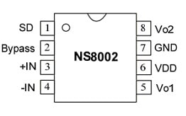
NS8002 IC Pin Configuration
- Pin 1 (SD): Shutdown or power-down control input. The amplifier enters its shutdown state when the specified shutdown logic level is applied.
- Pin 2 (BYP): Bypass pin used to establish the internal common-mode reference. A bypass capacitor is normally connected to this pin.
- Pin 3 (+IN): Non-inverting input of the first amplifier stage.
- Pin 4 (IN−): Inverting input of the first amplifier stage. The input signal and feedback network are connected to this pin according to the application circuit.
- Pin 5 (Vo1): First amplifier output and one side of the BTL speaker connection.
- Pin 6 (VDD): Positive power-supply input.
- Pin 7 (GND): Ground connection.
- Pin 8 (Vo2): Second amplifier output and the other side of the BTL speaker connection.
The Vo1 and Vo2 pins should be treated as a differential output pair. Neither output should be directly connected to ground when the amplifier is operating in BTL mode.
Features & Specifications:
The features and specifications of NS8002 IC include the following.
The main features and specifications of the NS8002 include:
- Class-AB audio power amplifier.
- Bridge-tied-load (BTL) output configuration.
- 8-pin SOP package for the referenced device.
- Low-voltage operation suitable for portable audio applications.
- Externally configurable voltage gain.
- Shutdown/power-down control.
- No external output coupling capacitor is required for the BTL output.
- Gain-bandwidth product of up to approximately 2.5 MHz, according to the referenced device specifications.
- Low shutdown current, specified at approximately 1 µA under the applicable test conditions.
- Operating temperature range of approximately −40°C to +85°C, according to the referenced specifications.
- Junction temperature specified up to approximately 150°C.
- Input voltage should remain within the limits specified in the manufacturer’s datasheet.
- Storage temperature is specified over a wide range, typically from approximately −65°C to +150°C for the referenced device.
Output Power
The output power of an audio amplifier should always be specified together with its test conditions.
For the referenced NS8002 device, an output of approximately 3 W into a 3 Ω BTL load at a 5 V supply is specified under a 10% THD condition.
A lower output-power value may be specified under different supply voltage, load impedance, or distortion conditions. Therefore, output-power figures from different parts of a datasheet should not be compared without checking their test conditions.
Equivalents & Other Power Amplifier ICs
The term “equivalent” should be used carefully for audio amplifier ICs. Two devices are not necessarily interchangeable simply because both are audio amplifiers.
A suitable replacement should be checked for:
- Supply-voltage range
- Output power
- Speaker/load impedance
- Package type
- Pin configuration
- Gain
- Shutdown control
- Output configuration
- Thermal characteristics
Other audio amplifier ICs may be used as alternatives depending on the requirements of the application. However, devices such as TDA2003, LM4562, or audio codecs should not automatically be described as direct equivalents because their functions, supply requirements, packages, and output capabilities can be different.
Similarly, other devices carrying an 8002/8002A/8002B-type designation may not be pin-compatible with the particular NS8002 device discussed here. For a replacement design, the manufacturer’s datasheet should always be consulted before substituting another IC.
NS8002 IC Block Diagram
The NS8002 internal architecture consists of two amplifier stages configured to produce a differential BTL output.
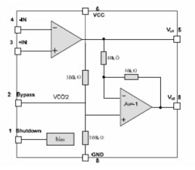
Block Diagram
The first amplifier stage uses external feedback components to establish the required closed-loop gain.
The second amplifier stage produces the complementary output required for differential speaker drive.
For the referenced configuration, the differential voltage gain can be expressed as:
AVD = 2 × Rf/Ri
where:
- AVD = differential voltage gain
- Rf = feedback resistance
- Ri = input resistance
The factor of two results from the BTL configuration, where the two amplifier outputs move in opposite directions.
BTL Operation
In a conventional single-ended amplifier, one side of the speaker is connected to ground while the amplifier drives the other side. In a BTL amplifier, both speaker terminals are driven by amplifier outputs.
For example, when Vo1 increases, Vo2 decreases. When Vo1 decreases, Vo2 increases. The speaker therefore sees the difference between these two signals.
This arrangement provides several advantages:
- A larger voltage swing can be developed across the speaker.
- Higher output power can be obtained from a low supply voltage compared with an equivalent single-ended configuration.
- An output coupling capacitor is not required because the two outputs have approximately the same DC common-mode voltage.
The speaker must therefore be connected between Vo1 and Vo2, rather than between one output and ground.
NS8002 Gain Calculation
This could become one of the strongest technical sections.
NS8002 Gain Calculation
Explain:
AVD = 2 × Rf/Ri
Then give a worked example.
For example, if:
- Rf = 20 kΩ
- Ri = 10 kΩ
then:
AVD = 2 × 20/10 = 4 V/V
Then explain how voltage gain in dB is calculated:
Gain(dB) = 20 log₁₀(AVD)
USB Audio Amplifier Circuit with NS8002 IC
The NS8002 can be used in a compact 5 V USB-powered audio amplifier when the supply voltage, speaker impedance, and other operating conditions fall within the manufacturer’s specifications. A typical application circuit uses the NS8002 together with a small number of external resistors and capacitors. The exact component values should be selected according to the required gain, input signal level, supply voltage, and speaker impedance.
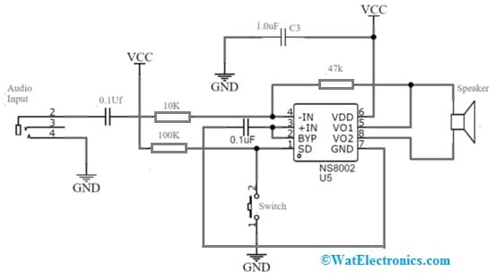
USB Audio Amplifier Circuit with NS8002 IC
Typical components used in an application circuit may include:
- NS8002 IC
- Speaker
- Power switch
- Input and feedback resistors
- Input coupling capacitor
- Bypass capacitor
- Power-supply decoupling capacitor
- USB 5 V supply or suitable regulated power source
The amplifier’s output should be connected between Vo1 and Vo2. The speaker should not be connected from either output pin directly to ground.
The maximum output power should also not be assumed simply from the USB supply voltage. It depends on the speaker impedance, distortion limit, supply capability, and the operating conditions specified by the manufacturer.
Working
The operation of the USB audio amplifier can be explained in several stages. The 5 V supply is connected to the VDD pin, while the ground connection is made to the GND pin. Appropriate supply bypassing should be provided close to the IC to reduce supply noise and improve amplifier stability.
The audio signal is applied to the input network. Depending on the circuit configuration, an input coupling capacitor may be used to block any DC component from the source. The bypass pin is connected to a suitable capacitor to establish a stable common-mode reference for the amplifier.
The first amplifier stage amplifies the input signal according to the gain determined by the external feedback network. The second amplifier stage generates the complementary output signal.
The loudspeaker is connected between Vo1 and Vo2. Because the two outputs are driven differentially, the voltage across the speaker is approximately the difference between the two output signals.
The shutdown pin can be controlled using a switch or another logic signal. The exact logic level required to enable or disable the amplifier should be implemented according to the manufacturer’s datasheet.
Important Design Considerations
When building a USB-powered NS8002 amplifier, several factors should be considered:
- Use a supply voltage within the specified operating range.
- Use a speaker impedance supported by the device.
- Place supply and bypass capacitors close to the IC.
- Keep the audio input wiring away from noisy digital or power wiring where possible.
- Do not connect either BTL output directly to ground.
- Consider PCB thermal dissipation when operating continuously at high output power.
- Do not exceed the IC’s maximum junction temperature.
- Verify the actual output power using the manufacturer’s specified test conditions.
The circuit can be used in compact audio equipment, portable speakers, educational electronics projects, and other low-power audio applications.
NS8002 IC Design Notes
When designing a circuit around the NS8002, the datasheet should be treated as the primary reference for component selection and operating limits.
In particular, verify the following before building the circuit:
- Supply voltage
- Speaker impedance
- Maximum output power
- THD at the desired output power
- Input signal amplitude
- Closed-loop gain
- Shutdown logic
- Thermal performance
- Package characteristics
- Recommended PCB layout and bypassing
These parameters are especially important when the amplifier is expected to operate continuously at relatively high output power.
NS8002 vs PAM8403
This is an excellent comparison topic because people choosing a small audio amplifier often encounter these two types of devices.
|
Parameter |
NS8002 |
PAM8403 |
|
Amplifier class |
Class AB |
Class D |
|
Output channels |
1 channel |
2 channels (stereo) |
|
Output configuration |
BTL |
Differential/BTL |
|
Package |
SOP-8 | SOP-16 |
| Supply voltage | About 3.0–5.25 V for the referenced NS8002 |
2.5–5.5 V |
|
Output power |
2.4 W @ 4 Ω, 10% THD for the referenced datasheet | Up to 3.2 W/channel @ 4 Ω, 5 V, 10% THD+N |
| Gain | Externally adjustable |
Fixed closed-loop gain in the referenced device |
|
Efficiency |
Class-AB architecture; lower than Class D in typical operation | Up to about 90% |
| Output coupling capacitor | Not required for BTL output |
Not required |
|
Shutdown/mute |
Shutdown control | Shutdown and mute controls |
| Thermal protection | Depends on the specific NS8002 version |
Thermal shutdown |
|
Short-circuit protection |
Verify specific NS8002 datasheet | Yes |
| Typical applications | Low-voltage mono audio systems |
Portable stereo speakers and compact stereo audio systems |
NS8002 Troubleshooting
NS8002 has no sound
Possible Causes:
- Incorrect supply voltage
- Shutdown pin in the wrong state
- Incorrect input wiring
- Missing bypass capacitor
- Speaker incorrectly connected
- Faulty speaker
- Excessive input attenuation
NS8002 output is distorted
Possible causes:
- Input signal too large.
- Speaker impedance too low.
- Supply voltage insufficient.
- Amplifier clipping.
- Excessive output power.
- Thermal limiting.
NS8002 IC gets hot
Possible causes:
- Low speaker impedance● Excessive output power
- Continuous operation near maximum output
- PCB thermal limitations
- Supply voltage outside the recommended range
Advantages of NS8002 IC
The main advantages of the NS8002 include:
- Low-voltage operation: Suitable for compact and portable audio equipment.
- BTL output: Provides differential speaker drive from a low supply voltage.
- No output coupling capacitor: The BTL configuration eliminates the need for a large output coupling capacitor.
- Configurable gain: External resistors can be used to set the required closed-loop gain.
- Shutdown function: Helps reduce power consumption when audio output is not required.
- Small package: Suitable for space-constrained circuit designs.
- Simple external circuitry: Only a relatively small number of external components are required.
Disadvantages of NS8002 IC
The main limitations include:
- Limited output power: It is intended for low-power audio applications rather than high-power speaker systems.
- Thermal limitations: Continuous operation at high output power can increase IC temperature.
- BTL output restrictions: The speaker must be connected between the two amplifier outputs, and neither output should be treated as a conventional grounded output.
- Speaker impedance limitations: The connected load must remain within the manufacturer’s specified range.
- Not universally pin-compatible: Other 8002-series or audio amplifier ICs may have different pin configurations and electrical characteristics.
Applications
The NS8002 can be used in a variety of low-voltage audio applications, including:
- Portable audio systems.
- Battery-powered speakers.
- Compact Bluetooth speaker designs.
- USB-powered audio amplifiers.
- Small multimedia speakers.
- Portable electronic equipment.
- Educational audio amplifier projects.
- Embedded audio systems.
- Small consumer electronics.
- Low-power speaker driver circuits.
For stereo applications, two amplifier channels are required—one channel for the left speaker and another for the right speaker.
FAQs
Is the NS8002 a Class-D amplifier?
No. The NS8002 discussed here is a Class-AB audio power amplifier.
Is the NS8002 a stereo amplifier?
A single NS8002 provides one BTL amplifier channel. A stereo system requires two independent amplifier channels.
Does the NS8002 require an output coupling capacitor?
No external output coupling capacitor is normally required when the IC is used in its specified BTL configuration.
Can the NS8002 be powered from USB?
It can be used in a 5 V USB-powered design when the supply voltage and all other operating conditions are within the device’s specified limits.
How is the speaker connected to the NS8002?
The speaker is connected between the two amplifier outputs, Vo1 and Vo2. It should not be connected between one output and ground in a standard BTL configuration.
Can another 8002 amplifier IC directly replace the NS8002?
Not necessarily. Devices with similar names can have different pinouts, electrical characteristics, supply ranges, and output capabilities. The specific datasheets must be compared before substitution.
Please refer to this link for the NS8002 IC Datasheet.
Conclusion
The NS8002 is a compact Class-AB audio power amplifier IC designed for low-voltage applications. Its BTL output configuration allows a speaker to be driven differentially while avoiding the need for an external output coupling capacitor.
The IC also provides configurable gain and a shutdown function, making it suitable for portable and space-constrained audio designs. A single device can be used for mono audio amplification, while two amplifier channels can be used to build a stereo system.
When designing an NS8002-based circuit, particular attention should be given to the supply voltage, speaker impedance, output-power test conditions, shutdown logic, gain-setting components, and thermal performance. Similar-looking amplifier ICs should not be assumed to be direct replacements without comparing their datasheets.
For the exact electrical limits, recommended component values, and application conditions, always refer to the manufacturer’s datasheet for the specific NS8002 device being used.