The 2SC828 is a silicon bipolar junction transistor that can be used as both an amplifier and a switch. It handles up to 100 mA of load current when used as a switch. This amount of current is sufficient to drive other components within an electrical circuit. This transistor delivers 400 mW of power and has a maximum DC gain (hFE) of 520 when used as an amplifier. The 2SC828 transistor can be used to drive ICs, LEDs, microcontrollers, high-power transistors, relays, etc. It is suitable for relatively low-current applications. Additionally, it can utilize this transistor in audio preamplifier circuits and amplifiers. This article provides an overview of the 2SC828 transistor, pinout, specifications, and its applications.
What is a 2SC828 Transistor?
2SC828 is a silicon-based AF amplifier transistor that belongs to the NPN transistor family, used for amplification and switching in AF audio equipment. This transistor offers high stability during medium-frequency switching operations. It is available in the TO-92 package and delivers highly stable operation wherever the medium-frequency type is used.
This NPN transistor is available in three different variants based on different hFE levels such as Q, R & S, which have hFE ranges from 130 to 260, 180 to 360, and 260 to 520, respectively. This transistor is mainly designed for low-power applications because it always provides 50 mA DC collector current.
While looking for a suitable transistor for your application based on several factors, it is very important to look into a few points on how to select a Transistor.
2SC828 Transistor Pin Configuration
The 2SC828 transistor pin configuration is shown below. This transistor includes three terminals; each with a specific function is discussed below.
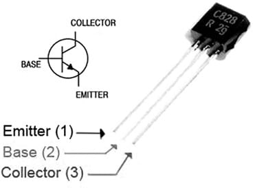
2SC828 Transistor Pin Configuration
- Pin-1 (Emitter): The emitter is the terminal that injects majority charge carriers into the base region.
- Pin-2 (Base): The base controls the transistor’s collector-emitter current and is used to control its operating state.
- Pin-3 (Collector): The collector collects charge carriers and is normally operated at a higher potential than the emitter in an NPN transistor.
Features & Specifications:
The features and specifications of the 2SC828 transistor include the following.
- It is an NPN transistor.
- It is available in the TO-92 package.
- Its collector-emitter voltage or VCEOis 25V.
- Collector current or IC is 0.2 A.
- Collector-to-base voltage or VCBO is 30 V.
- The emitter-to-base voltage is 7V.
- Its collector current is 0.05 A.
- Its power dissipation or Ptot is 500 mW.
- Collector dissipation is 0.4 W.
- DC current gain or hFE is 130.
- Maximum collector current or IC is 0.0500 A.
- The total current gain bandwidth is 220 MHz.
- The noise figure is 6 dB.
- Its operating and storage junction temperature ranges from -55 to +150°C
Equivalent and Complementary Transistors
Equivalent or alternative 2SC828 transistors are; 2N3394, 2SC1815, 2N3708, 2SC2458, 2SC2785, 2SC3114, 2SC2960, 2SC3198, 2SC3330, 2SC3199, 2SC3331, 2SC3383, 2SC3382, 2SC3916, 2SC3918, 2SC3917, 2SC3919, 2SC3921, 2SC3920, 2SC3922, 2SC536, 2SC3923, 2SC828A, 2SC828A-R, 2SC828A-Q, 2SC828A-S, 2SD1207, 2SC945, 2SD1347, 2SD545, 2SD1835, 2SD789, BC182LB, BC167, BC184L, C945, C1815, H945, KSC945C, KSC1815, KTC3199 or KTC3198. The complementary 2SC828 NPN transistor is a 2SA564 PNP transistor. SMD 2SC828 version transistor is MMBTH10 in the SOT-23 package.
Replacing a suitable transistor in any circuit based on the requirements is very important. To know the guidance of how to replace it, please refer to this; Replacing Transistors in Electronic Circuits: Factors and Considerations.
How to Use a 2SC828 Transistor Safely in a Circuit?
To use the 2SC828 Transistor safely in a circuit for reliable long time for reliable long-term operation, it is suggested not to drive any load above 100mA and 25V DC. Always utilize an appropriate base resistor and do not operate or store it in the range of -55 to +150°C.
Flyback Transformer Tester Circuit
The Flyback transformer tester circuit is relatively simple and inexpensive to construct. The required components to make this simple circuit include; 30V 100mA 2SC828/2SC2240 low noise NPN transistors. 0.047uF 63V and 0.022uF 63V polyester capacitors, resistors; 1.8K 1/4W, 1K 1/4W, 150K 1/4W, 10K 1/4W ,120K 1/4W, 470 ohm 1/4W and 1mA meter. Connect the components as per the diagram shown below.
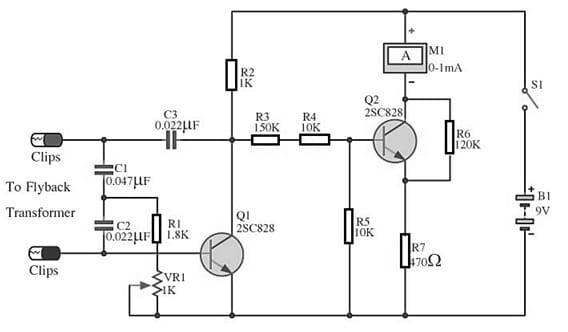
Flyback Transformer Tester Circuit
Working
The flyback transformer tester consists of several functional sections, including the oscillator circuit, the current amplifier, & detect circuits. The oscillator section uses a 2SC828 Q1 transistor. Its base is connected to the associated resistors and capacitors that establish the oscillator’s operating conditions.
Next, the current amplifier and detection circuits use the Q2 2SC828 transistor to amplify the detected signal and use resistors to limit the current through the ammeter. Finally, If a lower-current-range ammeter is selected, the R7 resistor should be adjusted accordingly.
To start with, place the two probes across the appropriate terminals of the flyback transformer then turn on switch S1. If the current is around 0.1 mA, then the oscillator may not start. Next, gradually adjust the variable resistor VR1 to reduce the resistance. If you read that the current value is approximately 0.4 mA, then it indicates that the oscillator circuit has already begun.
After that, touch the two probes together to observe that the meter reading should decrease. A short circuit in the flyback transformer can disrupt the operation of the oscillator circuit. When calibrating the transformers, adjust VR1 until the 1mA meter reads approximately 0.6 mA. Generally, the meter needle may fluctuate slightly. However, the meter indicator will drop if the transformer is shorted.
Connecting a base resistor to the base terminal of the transistor is important for limiting base current and preventing excessive current. Please refer to this link for; Choosing Base Resistance for Transistors in Electronic Circuits.
Advantages & Disadvantages
The advantages of the 2SC828 transistor include;
- This transistor provides high stability within medium-frequency switching operation.
- It is available mainly in three variants based on the different hFE ranges.
- It is a low-cost transistor.
- This transistor has a useful current gain and operating temperature range, making it suitable for low-cost and low-power applications.
- It is very simple to use because it is housed within a tiny TO-92 package.
The disadvantages of the 2SC828 transistor include the following.
- It has limited voltage and current handling abilities.
- This transistor’s frequency limitations may restrict its use in some high-frequency applications.
- Its electrical characteristics vary with temperature, which can affect circuit performance.
Applications
The applications of the 2SC828 transistor include;
- Engineers use this transistor in AF tuners, amplifier systems, and AM transmitter oscillator drivers, among other applications.
- You can configure it as one transistor in a Darlington setup, as well as in audio preamplifiers and signal-amplification circuits.
- Additionally, it serves effectively at the outputs of low-current IC circuits, provided its electrical ratings align with the requirements.
- This transistor switches low-current loads within the specified device ratings.
- Used in moderate-speed switching applications.
- Used in AM transmitter circuits and oscillator circuits to generate sine-wave or square-wave oscillators, depending on the circuit configuration.
Please refer to this link for the 2SC828 transistor datasheet.
In summary, this article has provided an overview of the 2SC828 transistor, pinout, specifications, and its applications. This transistor belongs to the NPN transistor family made with silicon-based material, used in applications such as audio frequency amplifier transistor & switching circuits. This transistor is capable of handling collector current within its specified rating. What is the MMBTH10 transistor, and how does it compare with the 2SC828