The MMBTH10 is an NPN silicon bipolar junction transistor (BJT) designed for high-frequency radio-frequency (RF) applications. It is commonly used in VHF and UHF amplifiers, RF mixer circuits, and high-output VHF oscillators. The transistor has a minimum transition frequency of 650 MHz and a maximum continuous collector current of 50 mA.
The MMBTH10 is available in a compact SOT-23 surface-mount package, making it suitable for space-constrained electronic designs. Its high-frequency characteristics make it useful in radio receivers, RF signal amplification stages, oscillator circuits, and experimental signal generators. In this article, we explain the MMBTH10 transistor pinout, features, electrical specifications, equivalent transistors, VHF oscillator applications, advantages, disadvantages, and practical design considerations.
What is an MMBTH10 NPN RF Transistor?
The MMBTH10 is an NPN silicon bipolar junction transistor intended primarily for VHF/UHF amplification, RF mixers, and oscillator applications. It operates by using a small base current to control a larger collector current.
The transistor has three terminals: the base, emitter, and collector. When the base-emitter junction is properly forward-biased, the transistor conducts current between the collector and emitter. With suitable biasing and external components, it can amplify high-frequency signals or provide the gain needed to sustain oscillations in an RF oscillator.
The MMBTH10 has a minimum transition frequency of 650 MHz under specified test conditions. However, this value does not guarantee useful amplification at every frequency below 650 MHz. Practical performance depends on operating frequency, bias current, circuit configuration, impedance matching, and stability.
While searching for an appropriate transistor for your application depending on a few features, it is very significant to refer to this – How to Select a Transistor.
MMBTH10 Pin Configuration:
The MMBTH10 is commonly supplied in a three-pin SOT-23 surface-mount package. Its standard pin assignment is shown below.
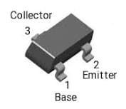
MMBTH10 Pin Configuration
|
Pin Number |
Pin name |
Function |
|
Pin 1 |
Base (B) | Controls collector current through the base-emitter junction. |
| Pin 2 | Emitter (E) |
Provides the emitter terminal; it is commonly connected to ground in an NPN common-emitter circuit. |
|
Pin 3 |
Collector (C) |
Connects to the collector load or supply network and commonly provides the output in a common-emitter amplifier. |
Check the manufacturer’s package drawing to confirm the viewing orientation and pin numbering before assembling a circuit.
Features & Specifications:
The MMBTH10 transistor features and specifications include the following.
- NPN silicon bipolar junction transistor.
- Designed for VHF, UHF, and RF applications.
- Compact SOT-23 surface-mount package.
- Minimum transition frequency of 650 MHz.
- Maximum collector-emitter voltage of 25 V.
- Maximum collector-base voltage of 30 V.
- Maximum emitter-base voltage of 3 V.
- Maximum continuous collector current of 50 mA.
- Minimum DC gain of 60 under specified test conditions.
- Maximum collector-base capacitance of 0.7 pF under specified test conditions.
- Suitable for RF amplifiers, mixers, and VHF oscillators.
MMBTH10 Electrical Specifications
The following table summarizes commonly published MMBTH10 specifications. The power-dissipation figure below refers to the Diodes Incorporated SOT-23 version; always consult the datasheet for the exact ordering code.
|
Parameter |
Symbol |
Specification |
|
Transistor type |
— | NPN BJT |
|
Package |
— |
SOT-23 |
| Collector-emitter breakdown voltage | VCEO |
25 V |
|
Collector-base breakdown voltage |
VCBO | 30 V |
| Emitter-base breakdown voltage | VEBO |
3 V |
|
Maximum continuous collector current |
IC | 50 mA |
|
Collector power dissipation |
PD |
225 mW, subject to specified thermal conditions |
| Minimum DC gain | hFE |
60 at IC = 4 mA, VCE = 10 V |
|
Minimum transition frequency |
fT | 650 MHz at IC = 4 mA, VCE = 10 V, f = 100 MHz |
|
Maximum collector-base capacitance |
Cobo |
0.7 pF at VCB = 10 V, f = 1 MHz |
| Operating junction temperature | TJ |
Typically −55°C to +150°C |
Difference Between MMBTH10 and MPSH10 Pinouts
The MMBTH10 and MPSH10 are related RF transistor types, but they are commonly available in different packages.
MMBTH10: Typically supplied in a three-pin SOT-23 surface-mount package, with Pin 1 as Base, Pin 2 as Emitter, and Pin 3 as Collector.
MPSH10: Commonly supplied in a three-lead TO-92 through-hole package, typically with Emitter, Base, and Collector leads when viewed in the orientation specified by the applicable datasheet.
Because package orientation and pin numbering differ, do not install an MPSH10 in an MMBTH10 PCB footprint without checking the datasheet and modifying the connections as necessary.
MMBTH10 Package Marking
The MMBTH10 SOT-23 device may carry the marking code 3EM. This marking can help identify the component on a circuit board, but top markings may vary by manufacturer or production variant. Confirm the marking against the relevant manufacturer’s datasheet before identifying an unknown component.
Important Specification Notes
- The 650 MHz transition frequency is a minimum value under the stated test conditions, not a guarantee of useful circuit gain at that frequency.
- The DC gain of 60 is a minimum measured at the specified collector current and collector-emitter voltage.
- The collector-base capacitance of 0.7 pF is a maximum value under the stated reverse-bias and frequency conditions.
- The 225 mW power-dissipation rating depends on the manufacturer’s specified thermal conditions and does not apply to every MMBTH10 variant.
- Maximum ratings are not recommended operating targets. Actual current and power must remain within the applicable electrical and thermal limits.
Equivalent and Replacements
When replacing the MMBTH10, compare the electrical ratings, transition frequency, current gain, capacitances, noise performance, package, and pin configuration. Potential replacement candidates for evaluation include:
MMBTH10LT1G: An onsemi ordering variant associated with the MMBTH10 RF transistor family. Confirm its datasheet specifications and package compatibility.
PMBTH10: A Nexperia RF transistor that can be evaluated as an alternative, subject to verification of the electrical characteristics and package.
MPSH10: A related RF transistor commonly available in a TO-92 through-hole package. It may be suitable for certain circuit designs but is not a direct mechanical replacement for an SOT-23 device.
General-purpose NPN transistors such as the BC547 and 2N3904 should not automatically be considered equivalent replacements. Although they can amplify or switch signals, their RF performance, capacitances, and pin configurations may differ significantly.
Before selecting a substitute, compare the relevant manufacturer datasheets and confirm that the device will operate correctly at the required frequency, voltage, current, and power levels.
To know how to replace a transistor, you need to refer to this link: Replacing Transistors in Electronic Circuits: Factors and Considerations.
MMBTH10 RF Amplifier Applications
The MMBTH10 is designed for RF amplifier applications in which high-frequency signal amplification is required. A typical amplifier uses the transistor together with biasing resistors, coupling capacitors, and suitable inductors or impedance-matching components.
The biasing network establishes the transistor’s operating point. An RF signal applied to the base produces variations in collector current, resulting in an amplified output signal at the collector.
In tuned amplifiers, inductors and capacitors can form a resonant network that selects the desired frequency range.
The actual gain depends on the transistor’s operating point, frequency, source and load impedances, circuit layout, and external components.
Important RF Amplifier Design Considerations
- Biasing: Establish a suitable operating point without exceeding the transistor’s ratings.
- Frequency selection: Choose inductors and capacitors appropriate for the intended frequency band.
- Impedance matching: Design suitable input and output networks where required.
- PCB layout: Keep RF connections short and minimize parasitic capacitance and inductance.
- Stability: Provide suitable grounding, supply decoupling, and isolation between the input and output.
- Thermal management: Keep the transistor within its electrical and thermal limits.
MMBTH10 in VHF Oscillator and Signal Generator Circuits
The MMBTH10 can also be used in VHF oscillator and signal generator circuits to generate high-frequency electrical signals. The transistor provides active gain, while a frequency-selective network determines the oscillation frequency.
An LC oscillator typically uses an inductor and capacitor to establish a resonant frequency. A feedback network returns part of the output signal to the input with the appropriate phase and magnitude to sustain oscillation.
The oscillation frequency can be adjusted by changing the capacitance or inductance of the resonant network. The actual frequency also depends on the circuit topology, transistor characteristics, component tolerances, and parasitic effects.
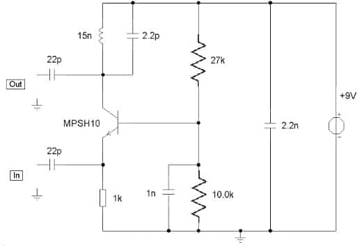
TV Preamplifier Circuit
Working Principle of a VHF Oscillator
The operation of an MMBTH10-based VHF oscillator can be understood through the following steps:
- Transistor biasing: A biasing network establishes the transistor’s operating point.
- Frequency selection: An LC resonant network determines the intended oscillation frequency.
- Signal amplification: The transistor provides the gain needed to compensate for losses in the resonant network.
- Positive feedback: A feedback network returns part of the output signal to sustain oscillation.
- RF output: The generated signal is taken from the circuit through a suitable output-coupling network.
Proper biasing, feedback, and impedance matching are essential for stable oscillation. Poor circuit layout or excessive feedback can cause unwanted oscillation, frequency drift, or unstable operation.
Connecting a resistor to the transistor’s base terminal in any circuit is compulsory to keep it from being damaged. To know more about that, please refer to this link: Choosing Base Resistance for Transistors in Electronic Circuits.
Applications of VHF Oscillator Circuits
An MMBTH10-based VHF oscillator can be evaluated for the following applications:
- RF signal generation for electronics experiments.
- Radio receiver testing and alignment.
- Laboratory oscillator prototypes.
- VHF communication circuit development.
- Testing and evaluation of tuned RF circuits.
A practical signal generator may also require output buffering, attenuation, filtering, and frequency measurement, depending on the application.
Circuit design note: The oscillator description above explains the operating principle rather than specifying a tested, ready-to-build circuit. Component values and the feedback topology must be selected and verified for the intended frequency and supply conditions before constructing a circuit.
Advantages of the MMBTH10 Transistor
The main advantages of the MMBTH10 include:
- High-frequency capability: Its minimum transition frequency of 650 MHz supports suitable RF designs.
- Compact package: The SOT-23 package helps reduce PCB size.
- Low collector-base capacitance: The maximum specified value of 0.7 pF under stated test conditions can help reduce capacitive loading in suitable high-frequency circuits.
- Versatile RF applications: It can be used in amplifier, mixer, and oscillator designs.
- Small-signal operation: It is suitable for circuits operating within its electrical and thermal limits.
Disadvantages of the MMBTH10 Transistor
The limitations of the MMBTH10 include:
- Limited maximum continuous collector current of 50 mA.
- Power dissipation constrained by package and thermal conditions.
- High-frequency performance is sensitive to PCB layout and impedance matching.
- Potential instability when feedback and grounding are poorly designed.
- Surface-mount assembly requirements that may make breadboard prototyping difficult. A suitable
- SOT-23 breakout board can simplify prototyping.
- No guarantee of direct compatibility with general-purpose transistors or devices in different packages.
MMBTH10 Transistor Applications
The main applications of the MMBTH10 transistor include:
- VHF amplifiers: Amplification of suitable very-high-frequency signals.
- UHF amplifiers: Small-signal amplification in appropriate ultra-high-frequency circuits.
- RF mixer circuits: Frequency conversion when the transistor meets the circuit’s performance requirements.
- VHF oscillator circuits: Generation of RF signals using a suitable feedback and resonant network.
- RF signal generators: Experimental signal sources and oscillator prototypes.
- Radio receiver front ends: Amplification of received signals before subsequent processing.
- RF testing and measurement: Experimental circuits used for RF development and laboratory evaluation.
- Communication equipment: Small-signal RF stages in suitable communication designs.
The MMBTH10 should be selected according to the actual frequency, gain, noise, stability, and power requirements of the intended application.
MMBTH10 Datasheet
Before designing a circuit, consult the manufacturer’s datasheet for the exact MMBTH10 part number. The datasheet provides the package drawing, pin configuration, absolute maximum ratings, electrical characteristics, transition frequency, capacitance specifications, and thermal limitations.
Refer to the Diodes Incorporated MMBTH10 product page for manufacturer-specific documentation. For alternatives, consult the respective datasheets from onsemi and Nexperia before substituting an MMBTH10 with another RF transistor.
Please refer to this link for the MMBTH10 Transistor Datasheet.
Frequently Asked Questions
1. What is the transition frequency of the MMBTH10 transistor?
The MMBTH10 has a minimum transition frequency of 650 MHz, measured at IC = 4 mA, VCE = 10 V, and f = 100 MHz.
2. What is the maximum collector current of the MMBTH10?
The commonly specified maximum continuous collector current is 50 mA. The actual operating current must remain within the device’s electrical and thermal limits.
3. What is the pin configuration of the MMBTH10?
For the standard SOT-23 version, Pin 1 is Base, Pin 2 is Emitter, and Pin 3 is Collector. Always confirm the package drawing for the exact manufacturer’s part.
4. Can the MMBTH10 be used in a VHF oscillator?
Yes. The MMBTH10 is suitable for appropriately designed VHF oscillator circuits. The circuit requires suitable biasing, feedback, and a frequency-selective network.
5. What is the maximum collector-base capacitance of the MMBTH10?
The specified maximum collector-base capacitance is 0.7 pF at VCB = 10 V and f = 1 MHz.
6. Is the MMBTH10 interchangeable with the MPSH10?
They are related RF transistor types, but they are commonly available in different packages. The MPSH10’s TO-92 leads are typically arranged Emitter, Base, and Collector in the manufacturer’s specified viewing orientation, while the MMBTH10 uses the SOT-23 pin assignment. Verify the datasheets before substitution.
7. Can the MMBTH10 be used as an RF amplifier?
Yes. It is designed for RF, VHF, and UHF amplifier applications when the circuit is designed to meet the required gain, frequency, stability, and operating limits.
8. What determines the frequency of an MMBTH10 oscillator?
The oscillation frequency is primarily determined by the resonant network’s inductance and capacitance. Transistor characteristics, circuit topology, component tolerances, and parasitic effects also influence the actual frequency.
Conclusion
The MMBTH10 is an NPN RF transistor designed for VHF/UHF amplification, RF mixers, and high-output VHF oscillators. Its minimum transition frequency of 650 MHz, maximum continuous collector current of 50 mA, and compact SOT-23 package make it useful in suitable high-frequency electronic designs.
The transistor can also be evaluated for VHF oscillator and signal generator circuits, where an LC network determines the frequency and a feedback network sustains oscillation. Correct biasing, impedance matching, PCB layout, and thermal management are essential for reliable performance.
Always verify the package pinout, electrical specifications, and circuit operating conditions against the manufacturer’s datasheet before constructing an MMBTH10-based circuit.