Basics of Power Amplifier
Power amplifier are the basic category of amplifiers which is used to amplify the power of the input signal which may be either a digital signal or an analog signal from few milli watts to several milli watts depending on the need of amplification. These types of amplifiers are found in almost every analog to digital devices sorrounding us. From radio tuners to microwave to laptops to cell phones use power amplifiers in some form or the other.
What is a Power Amplifier?
The amplifier that has the property of converting the applied DC power that comes from the supply into AC power so that the load is provided with the sufficient amount of power, these types of amplifiers are defined as power amplifiers. In this case of amplifiers, the magnitude of the applied power tends to increase. Hence these amplifiers are used in various applications where the power requirement is to drive the load.
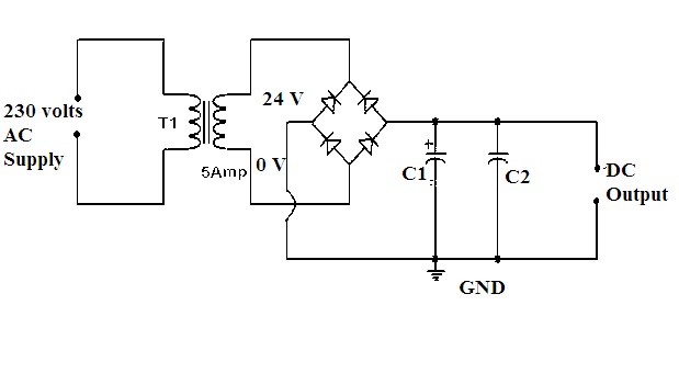
Power Amplifier Circuit Diagram
Types:
The amplifiers are classified based on the applied signals either it is the voltage signal or the power signal. This can be done based on the obtained characteristics of the input values and the output values. The type of devices that are connected to the amplifiers results in its classification as
1. Audio Power Amplifiers
The amplifiers where the amplification is required to amplify the audio signals are known as audio power amplifiers. In the headphones, transmitters, radio devices etc… these amplifiers are utilized. For example, the signal is of milliwatts after amplification it has the capacity of converting it into thousands of watts.
2. Radio Frequency Power Amplifiers
This type of amplifier is used frequently in long distances transmissions, that is the transmission over wireless media. The transmission of such signals requires amplification so that the strength of the signals can be improved and the data can be transmitted to long distances. These amplifiers are most widely used for the FM signals broadcasting.
3. DC Power Amplifiers
These amplifiers are used to amplify the Pulse Width Modulated signals. In this width of the pulse is modulated so that logic signals can be given to the motors to work based on it. The input will be taken from micro-controller units and the power of it will be increased and provides the amplified signals to the motors of DC type.
Classes of Power Amplifier
In multiple ways, the circuit of the power amplifier can be designed. Each circuit design possesses different characteristics as well as it produces various outputs. So to differentiate these amplifiers the classification is done in the alphabetical order.
The input signals that needs to be amplified can be either an analog signal or a digital signal. Based on that the power amplifer is classified as ClassA, B, AB or C and D, E, F,T etc… . For Analog signals either ClassA, ClassB, ClassAB, ClassC power amplifier are used. For digital signals ClassD,ClassE, ClassF power amplifiers are used.
1. Class A:
In this class of amplification, the signals of alternating current that consists of both positive and the negative halves are amplified by the single transistor in the circuit. Hence the construction of the class A circuit is simple in design. Because of this reason these amplifiers are the most frequently used one.
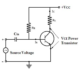
Class A Power Amplifier Circuit
The drawback of this circuit is that the transistor present in this circuit remains always on as it conducts in both positive and negative cycle of the input signal. Since the transistor is active for both the half cycles it dissipates lots of heat and this results in the decrease in the overall efficiency of the circuit. It also requires a heat sink to absorb the heat dissipated by the circuit. The angle of conduction for this class of amplifier is considered to be 360 degrees. The distortion in this type of amplifier is said to be minimum which results in better performance.
2. Class B
To overcome the drawback of the unnecessary heating of the device class B circuit of the power amplifier was designed. Rather than using the single transistor, in this circuit it is designed with the help of the two transistors( one NPN and other PNP) that complement each other.
The angle of conduction for these kinds of class amplifiers is 180 degrees. Therefore one half of the cycle that is positive cycle is amplified by one transistor and the remaining half that is the negative cycle is amplified by the second transistor. The corresponding transistor gets ON when the respective halves are amplified and thereby the overall signal gets amplified.
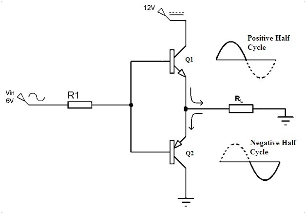
Class B Power Amplifier Circuit
In this way, the efficiency compared to the class A amplifier is improved to 70 percent (theoretically). These are mostly preferred for the devices that operate with the help of batteries. But here the two transistors follow superposition that leads to the distortion over the cross-region. These kinds of distortions was taken care in the design of class AB amplifiers.
3. Class C
This class of amplifiers possesses greater efficiencies but the design gets compromised because it goes through severe distortions. The greater efficiencies but the lesser are the conduction angle that is up to 90 degrees.
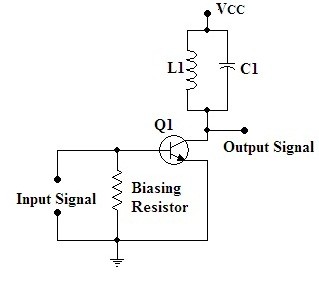
Class C Power Amplifier Circuit
As the signal generated from this circuit is of maximum distortion it cannot be preferred for the amplification of the audio signals. It is preferred in the oscillators that have frequency consisting high in range. It consists of the tuning load through which the input signals are filtered and amplified. Other than the considered frequency rest of the frequency signals are suppressed. This type is used for frequency modulation of the signals which are required for FM transmissions.
In this way, the various classes of the amplifiers are designed and discussed. There are other classes such as class D, Class E, class F, etc… where the pulse width modulated signals are amplified. These classes are generally preferred during switching applications or digital logic operations.
Applications:
There are wide varieties of applications of these amplifiers in the various sectors.
• These are used in varieties of devices such as headphones, microwave ovens, home theater systems, etc… these are the most important part of the basic electronics that comes under the category of the consumer’s range and household needs.
• To control servo motors and the specific DC motors the power amplifiers are utilized.
• As the wireless transmission requires high-frequency range for the transmission of the signals over a long distance the power amplification is beneficial in such cases. Higher the levels of power higher the transfer rate of data and its usability.
• It is also utilized in the types of equipment designed for the communication of the satellites.
Please refer to this link to know more about Regulated DC Power Supply MCQ’s & Transistor Audio Power Amplifiers MCQs
Please refer to this link to know more Power Amplifier MCQs
Hence the above are some of the applications of power amplifiers in the various fields.
Now after discussing all the basic things that relate to power amplifiers can you describe the design criteria of class AB amplifiers?