The LM3914 IC was designed in the late 1970s by National Semiconductor. So this IC is intended mainly to make and operate displays that show analog signal’s magnitude like; visual indicators or bar graphs. It can drive up to 10 LEDs, vacuum fluorescent displays, and LEDs on its outputs. Thus the output thresholds linear scaling will make the device work like a voltmeter. It provides a ten-step scale within the fundamental configuration that is expandable to more than 100 segments with other series of LM3914 ICs like LM3915, LM3916, etc. Thus, this article discusses an overview of LM3914 IC, pin configuration, specifications, and applications.
What is LM3914 IC?
The LM3915 monolithic IC is from the LM391x series and is well known for its precision, flexibility, and ease of use. So the main function of this IC is to convert the levels of analog voltage into a digital amount to drive LCD, LED, and many more within a dot mode or bar graph display. This is a low-powered IC that can be powered with a single power supply that ranges from 3Volts to 25Volts but its usual standby current supply is 1.6 Amps. Thus this IC can be used in amateur electronic projects and professional audio equipment.
The LM3915 IC utilizes a ten-stage voltage divider to light up LEDs in reply to analog voltage levels where each LED represents a 3 dB change within the power level of the signal. So this IC can be displayed in either bar mode or dot mode & the LED drive current can be set through peripheral operation.
LM3914 IC Working
The LM3915 IC is a driver IC and voltage level indicator that is used commonly to display the levels of analog signal on a series of LEDs (or) LED bar graph displays. Thus this IC works by contrasting the i/p voltage to a reference voltage and generates a signal that triggers the suitable indicator or LED.
This monolithic IC includes an internal voltage reference that can be regulated to set the range of display & a choice between linear and logarithmic scaling of the range of display. The LM3915 IC includes 10 outputs which drive up to 30mAmps of current each by allowing it to drive up to 10 LEDs (or) other visual indicators. So the output pins of this IC are arranged in a logarithmic or linear order based on the preferred scaling mode.
This IC operates in two modes either bar mode or dot mode which is determined through the MODE pin. So a series of LEDs in bar mode light up to form a bar graph which shows the overall input signal level whereas in dot mode, a single LED is only illuminated at a time that indicates the most important segment.
LM3914 IC Pin Configuration:
The pin configuration of LM3914 IC is shown below. So this IC includes 18 pins which are explained below.
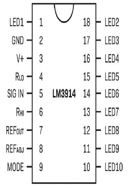
LM3914 IC Pin Configuration
- Pins – (1 & 10 – 18): These pins include LED1 and LED2 to LED10 where these pins help in controlling LEDs which have to be controlled.
- Pin-2 (V- / GND): This is the GND pin of the IC.
- Pin-3 (V+ / Vcc): It is a voltage supply pin that ranges from 3 to 18V.
- Pin-4 (RLO): It is a low-level voltage pin for a potential divider.
- Pin-5 (Signal): It is an analog signal i/p pin depending on which the light emitting diode is controlled.
- Pin-6 (RHI): It is a high-level voltage pin for a potential divider.
- Pin-7 (REF OUT): It is a reference output voltage pin used for the current limiting of LED.
- Pin-8 (REF ADJ): It is a voltage reference adjust pin.
- Pin-9 (Mode): It is a mode select pin between Bar/Dot modes.
Features & Specifications:
The features and specifications of LM3914 IC include the following.
- It is an analog-controlled LED driver IC.
- It has 10 controllable LEDs:
- This IC’s operating voltage ranges from 3V – 18V.
- Input analog voltage ranges from 1.2V to 12V.
- LED sink current ranges from 2mA to 30mA.
- It works in both Dot or Bar modes.
- This IC can be cascaded for controlling up to 100 LEDs.
- This IC is available in 18-pin PLCC and DIP packages.
- It changes the levels of analog voltage into visual LEDs.
- It is ideal for VU meters, audio level indicators, battery charge displays, and more.
- Its dimensions change based on package type.
- This IC has an internal voltage divider network used for LED activation.
- It has current-limiting resistors mainly for reliable LED brightness.
- It has a wide temperature range for consistent performance.
- This IC has less power consumption and is suitable for battery-powered applications.
- It independently operates without a microcontroller.
- Its internal integrated divider network shortens calibration.
- Its typical LED o/p current is 10 mA for each LED.
- Its typical i/p voltage range is 0V to Vref.
- The typical logarithmic range is 3 dB/step.
- The typical linear range is 1 dB/step.
- Commercial temperature range is from 0°C to 70°C & Industrial temperature range is -40°C to
- 85°C.
- It has output buffers for driving external loads.
- It needs external resistors typically for LED current setting & reference voltage.
Equivalents & Others
Equivalent LM3914 LED driver ICs are; LM3915 & LM3916 whereas alternative LED driver ICs are; MAX7219, CD4511, CD4054, etc.
Battery Level Indicator Circuit with LM3914 IC
In the automotive industry, the battery charging level indication is extremely required. Now particularly the designers are working on battery-operated automobiles. So it is an important job to work on the car battery by connecting a battery level indicator to make the cars easy to use.
Here we are designing a battery-level indicator circuit with LM3914 IC which is generally used to turn on a display that shows the analog signal’s magnitude visually. So this signal IC is used to drive several displays like LCDs, 10 LEDs, etc. Thus, the required components to make this battery level indicator circuit mainly include; an LM3914 IC, 1K resistor, 50K and 10K Potentiometers, 10 LEDs, and power supply.
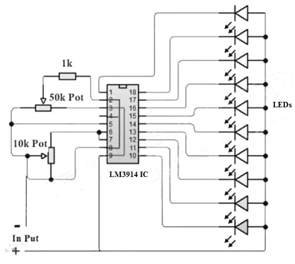
Battery Level Indicator Circuit with LM3914 IC
Working
The first step is to place an LM3914 chip on your PCB. So connect a resistor & both potentiometers accordingly. After that, all the LEDs need to be connected & a connector to connect to supply. Now this circuit needs to be calibrated for a 3.7Volts battery. For that, connect the power supply and provide 4Volts from it & regulate the potentiometer.
First, connect the 80% charge 3.7V battery supply and monitor the LEDs. After that connect the similar battery with 90% charge & examine the LEDs. Thus, you may monitor the slight changes. Finally, use the 100% charged battery and monitor the complete LED glow.
Thus, to calibrate this circuit, need to provide the power supply & adjust VR1 so that the first LED starts glowing. So the acceptance of different colored LEDs makes it clearer to identify the voltage level depending on the calibration ended. So you will notice the different glow patterns at different levels of the battery.
Thus, this circuit is used in automotive applications, the mobile phone industry, and portable electronic gadgets.
Advantages & Disadvantages
The advantages of LM3914 IC include the following.
- LM3914 IC is simple to use and utilizes fewer external components in digital circuitry
- These are versatile and use less power.
- These ICs have an internal voltage reference.
- These ICs provide precise LED output.
- It controls LED brightness.
- It operates in multiple modes like; dot mode & bar mode.
- This IC input voltage range is wide.
- It provides linear & logarithmic scaling.
- These can be utilized as analog meter circuits using simple external circuitry.
The disadvantages of LM3914 IC include the following.
- LM3914 IC can drive only 10 LEDs maximum which is not enough for some applications that need more LEDs.
- This IC does not supply a wide range of brightness control.
- Its voltage range is limited, which may not be suitable for applications that need higher voltages.
- This IC has a limited current drive, so it is not suitable where higher current levels is necessary.
Applications
The applications of LM3914 IC include the following.
- LM3914 IC is used in audio level indicator to display audio signal range within a bar graph format.
- It is used it indicate the charge level of the battery with a visual indication.
- It is used in signal strength meters to visualize the incoming RF signal strength within RF circuits.
- This IC displays the power source’s voltage level by monitoring the conditions of the power supply.
- It is used in temperature displays to show the level of temperature by using external sensors.
- This IC is used in audio equipment and amplifiers to indicate output power levels.
- It is used in light intensity displays to display the ambient light intensity.
- This IC is used to show an input signal’s frequency with suitable circuitry.
- This IC displays the speed of the motor depending on analog feedback signals utilized in motor control-based applications.
- When these ICs are connected with suitable sensors then it displays the level of liquid within water tanks.
- It indicates the rotating objects speed like fans, motors, etc.
- This IC is used with sensors to specify proximity to a surface or an object.
Please refer to this link for the LM3914 IC Datasheet.
Thus, this is an overview of LM3914 IC which is a versatile and broadly used IC that plays an essential role in a variety of applications that need precise & visual analog signal measurement. So these ICs are capable of driving a display of LEDs straight by providing an accessible solution for signal-level visualization. This it is a popular choice within power monitors, audio systems & other projects wherever visual feedback is necessary. Here is a question for you, what is LM3916 IC?