In the domain of electrical and electronics technology, the voltmeter is the crucial device that is extensively applied across various applications for measuring voltage valves. These voltmeters are available mainly in two types analog and digital. Analog voltmeters consist of a pointer that moves on the dial as per the measurement and displays the corresponding reading. With the advancements in technology and rapid development of digital systems, analogue voltmeters are being replaced by digital voltmeters. So, today this article focuses on explaining the working principle of the digital voltmeter, its block diagram, types, benefits, and applications.
What is a Digital Voltmeter?
Similar to an analog voltmeter, the digital voltmeter is used for the measurement of potential differences between two specific points in an electric circuit. The voltage that has to be measured can be either alternating or direct current and the measured value is displayed as discrete numerals. The numerical displays are so precise as there will be no observational mistakes committed by technicians or operators and also no pointer deflection takes place.
The digital voltmeter is abbreviated as DVM and this device holds numerous applications across multiple domains. With the progressing changes in IC technology, it became a possibility to lessen the size, pricing, and power requirements of DVMs. The precision of the digital voltmeter gets affected by multiple aspects such as power supply, variation in the input impedance levels, and temperature.
High-accuracy DVMs hold input resistance in the range of 1 GΏ or more for the minimum voltage levels ( which is < 20V), whereas less accurate DVMs hold input resistance in the range of 10MΏ. In order to make sure that the digital voltmeter precision lies within the manufacturer’s tolerance ranges, then the device has to be regularly calibrated in contrast to the voltage standards.
DVM Block Diagram and Working Principle
This section explains digital voltmeter parts and how the device works. The below picture shows the block diagram of the digital voltmeter.
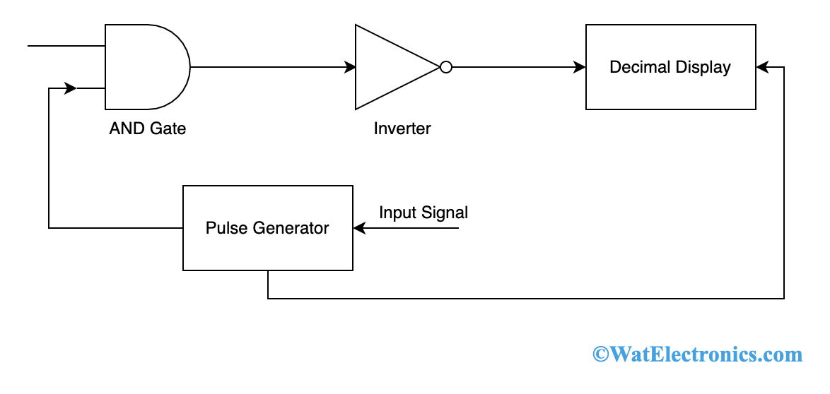
DVM Block Diagram
Input Signal – This is the signal which is given as input to the device for which the voltage level has to be measured.
Pulse Generator – This is the voltage source device that works with AC, DC, or both approaches to give output as a rectangular pulse. The levels of frequency and width of the generated rectangular pulse can be regulated using digital circuitry present inside the generator. Whereas the levels of rising and falling time are managed by analog circuitry.
AND Gate – As we know that the output of AND gate is HIGH only when both of its inputs are HIGH. When a train pulse along with the rectangular pulse is provided as input to the AND gate, then the output is in the form that train pulses have the same duration as the rectangular pulse.
Decimal Display Section – This section is used to count the total number of impulses and the duration in between the impulses. Then the count is displayed on either an LED or LCD screen after calibration.
Now, the working of DVM is explained as follows:
- An unknown voltage signal is provided as input to the pulse generator. Here, the output is a pulse where its width is the same as the input signal.
- The generated output from the pulse generator is given as one input to the AND gate and the other input to AND gate is a sequence of pulses.
- The output of AND gate is a positive triggered sequence of pulses having similar width as that of the pulse provided by the pulse generator.
- Now, the positive triggered pulse output is fed as input to an inverter which then inverts the output of the AND gate.
- Now, the inverter’s output is given provided to the counter device where it counts the total number of triggers in that duration. This is the same as the input signal.
- Now, to have a precise measurement the counter device has to be calibrated and it shows a direct voltage reading in volts.
With the working principle of the digital voltmeter, it is observed that it works in the same way as an analog to a digital converter where it transforms the analog input signal into a sequence of pulses and the count of pulses is directly proportionate to the input signal. Thus a DVM can be constructed even using A/D conversion techniques.
Types of Digital Voltmeter
Depending on the type of analog to digital conversion techniques, DVMs are classified into various types which are clearly explained in the below section.
Ramp Type Digital Voltmeter
The working of ramp types DVM is essentially dependent on the measurement of time. The device consists of a ramp generator that produces a signal that represents a ramp. Because of the ramp generator used in this circuit, the device is named ramp type DVM.
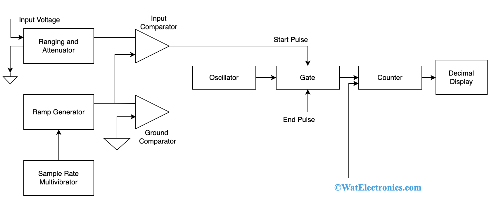
Ramp Type DVM
As the device operation is dependent on measurement of time where a linear ramp voltage signal is considered to transform from the input signal voltage level. In order to know the time interval, an electronic type of time interval counter device is used in the circuit where it displays the measurement in digits format thus indicating the voltmeter’s output.
- The measurement of voltage in this device is initiated by providing an unknown voltage signal to the ranging and attenuation section which either amplifies or attenuates the signal as needed.
- Also, from the ramp generator, either a positive or negative ramp voltage signal is considered. Let us consider a negative ramp signal which will be compared with the unknown signal.
- The amplified or attenuated signal is given to a comparator that compares both the ramp and unknown input signals.
- During the comparison, when the input voltage matches with ramp voltage, then a pulse is generated which opens the gate. With respect to time, the ramp voltage tends to decrease until it reaches ‘0’ voltage. Now, the ground comparator delivers a pulse to close the gate.
- The time period between the opening and closing of a gate is termed a gating time interval. During this time interval, the pulses from the clock generator pass through the gate and those will be counted by the counter and displayed.
- The oscillator generates clock pulses which are permitted to get through the gate to a counter where it is a counter for the total number of pulses passed through the gate.
- The sample rate multivibrator specifies the rate when the measurement cycles are initiated and is used to provide the initiating pulse for the ramp generator to initiate the next ramp voltage signal.
Integrating Type Digital Voltmeter
Here, the device measures the exact value of the input voltage corresponding to the constant measurement of time. In this circuit, a voltage-to-frequency converter device is employed where it operates on a feedback control system.
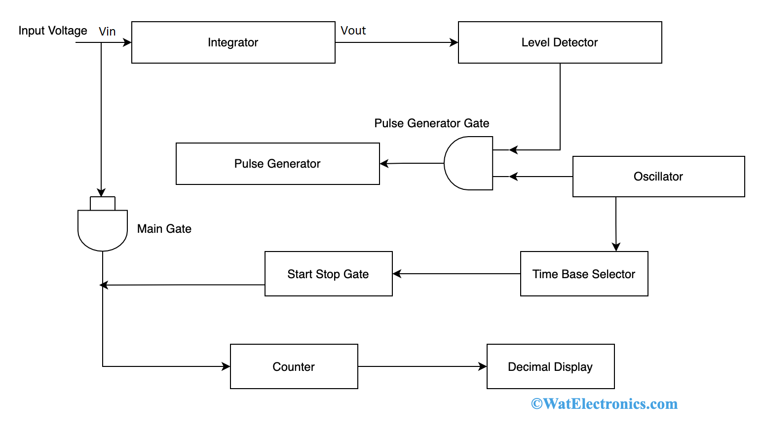
Integrating Type Digital Voltmeter
- The unknown input voltage Vin is fed to the integrator and the output voltage Vout tends to rise which is then applied to the level detector.
- When the output voltage reaches a specific reference level, then the detector transmits a pulse to the pulse generator gate.
- The output from the integrator is now compared with the fixed level voltage of the internal reference source and when Vout reaches the fixed voltage level, then the detector delivers the output pulse.
- The output from the level detector opens the gate which permits pulses generated from the oscillator to pass through the pulse generator. The pulse generator works like a Schmitt trigger where it provides fixed width and amplitude for each pulse that it receives. So now the input to the integrator is of opposite polarity. Because of this, the output voltage Vout gets back to its original voltage.
- As the output voltage is less than the reference voltage of the level detector, the pulse generator receives no output from the detector and the gate moves into a disabled state. Whereas when the pulse passes through the generator, Vin will get back to the original value and tends to rise. This repeats the cycle and shows a sawtooth waveform.
- So for each cycle of the sawtooth wave, a pulse is generated and the total number of pulses generated for the specific time period. This is known by counting the pulses in the specified time interval.
- The time base selector receives input from the oscillator that selects the duty ratio of required pulses. The first pulse passes through Start/Stop gate and the output from this is given to the main gate which means that pulse generator output also passes through the main gate.
- The subsequent pulse from the time base selector stops the Start/Stop gate thus disabling the main gate too. With this, the counter displays the total number of pulses that have passed in the specified time period which is a measurement of voltage that has to be measured.
Successive Approximation Digital Voltmeter
In this type of DVM, the output generated from DAC is compared with respect to the unknown voltage and the device holds the ability to measure 100 readings per second.
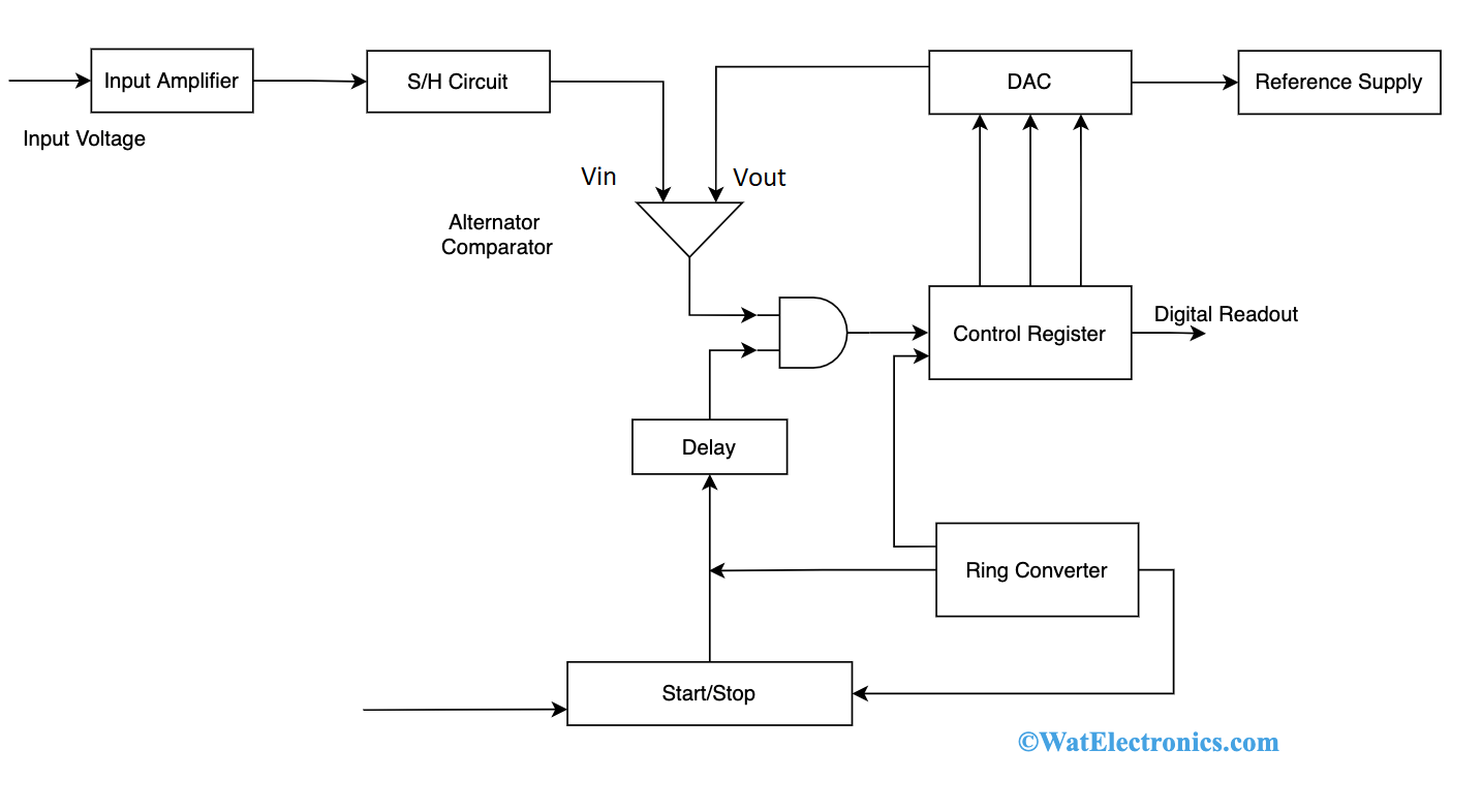
Successive Approximation DVM
- This device has an input amplifier to choose a required range of input voltage and to eliminate any noise levels. From the amplifier section, the input is fed to the comparator using an S/H circuit
- The control register (SAR) receives 8 bits as input from the counter circuit after every clock pulse which is then provided to DAC that converts the received signal into an analog voltage.
- Now, the comparator receives an analog signal as a second input and the output of AND gate becomes logic ‘1’ when the comparator’s output is positive.
- In the end, the digital output is received from the control register. The input levels get varied because of digitization and to get rid of this error a sample and hold circuit is placed.
- For example, consider the input as 8 bits. At the very first clock pulse, the control register sets the MSB bit D7 to 1 which gives the output of the control register as 10000000.
- When the Vout > Vin, the output of the comparator is negative and this resets the D7 bit.
- When the Vout < Vin, the output of the comparator is positive and this sets the D7 bit. In a similar manner, D7 to D0 bits are set and the process continues. So, the 8-bit input is converted
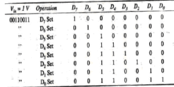
SAR Working
Dual Slope Integrating Digital Voltmeter
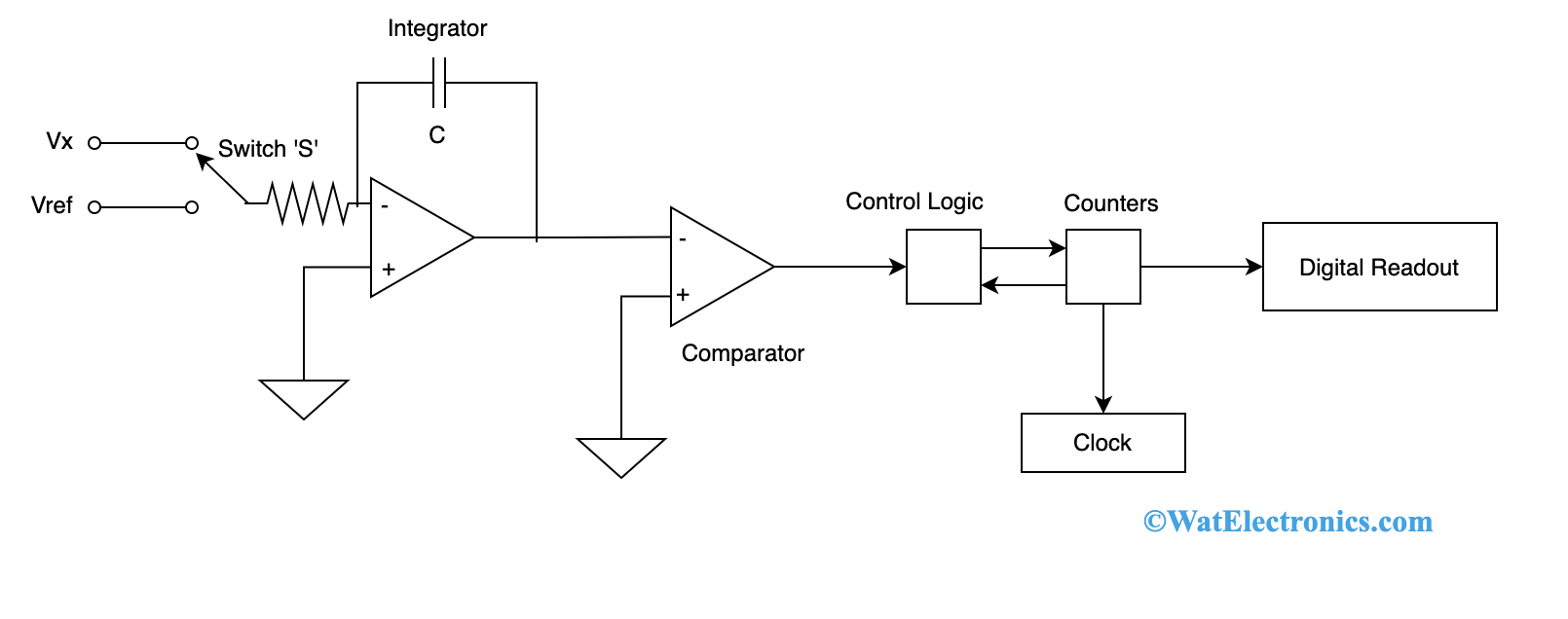
Below is the block diagram that explains the working of dual-slope integrating DVM.
Dual Slope Integrating Type DVM
Here, an unknown voltage is provided as input to the integrator circuit through switch ‘S’ for the specific time period. This time period is known by measuring the clock frequency in decimal counter devices.
During this time period, C gets charged is proportional to the input voltage Vx. After the end of time period T, the switch ‘S’ will be shifted from Vx to Vref which has opposite polarity to Vx. The charging of the capacitor tends to lessen with respect to time and finally appears in a downward linear ramp voltage.
Then for the second time period (known voltage), Vref is noted down for unknown time ‘t’. Here, the ‘t’ is known by counting a number of timing pulses from the clock till voltage at the capacitor attains its basic reference. This results in a negative slope which is proportional to the magnitude of the input signal’s voltage and it is constant.
So, these are the types of DVMs that are employed in the measurement of voltage, resistance, and current values.
Advantages
When compared with the analog types of DVMs, digital voltmeters have numerous advantages. Below are the few advantages of a digital voltmeter.
- With the usage of digital voltmeters, errors happened by humans can be eliminated resulting in exact and precise readings.
- Readings can be taken without having the impact of external conditions like atmosphere, temperature, and others.
- DVMs provide enhanced reliability, stability dependability.
- No manual involvement is required to find out the readings.
- The output from DVMs can be provided to memory devices for the purpose of storage.
- Digital voltmeters are so versatile and inexpensive too.
- DVMs work with minimal power.
Disadvantages of Digital Voltmeter
Even though there are various advantages of DVM, these devices also have disadvantages and those are:
- DVMs operate either with an external power source or batteries and the output is based on the type of power source used.
- DVMs are included with digitizing circuits and these lessen the operational speed.
- When the voltage level exceeds the specified limit, then it leads to devise damage.
- Digital voltmeters might get heated up upon extended usage and this results in wrong readings.
- When there are any fluctuating readings, DVMs do not have the capability to calculate those and even show output with wrong readings.
- It is complicated for DVMs to observe transient voltage spikes.
Applications
The applications of DVM are:
- Using a digital voltmeter, the actual voltage levels of various components can be known easily.
- With the known voltage values from DVM, current levels can be found.
- With a digital voltmeter, one can check whether there is power in the circuit or not.
- Employing a DVM can be useful in knowing battery is drained or charged.
What can be measured with a digital voltmeter?
With a digital voltmeter, the potential difference between two points in any electrical circuit can be known.
What is a digital voltmeter used for?
A DVM is used to measure voltage either in AC or DC circuits. The readings can be so accurate and precise.
What is the range of digital voltmeters?
The range of input voltage varies between 1 to 1000 volts. It consists of either choosing automatic range or an overload indication.
What are the characteristics of a digital voltmeter used in a typical digital multimeter?
A DVM is a voltage-sensitive instrument and when implemented in any device, it shows the voltage reading in a numeric form showing no pointer deflections.
So, this is all about the concept of a DVM. This article has explained on digital voltmeter working principle, its block diagram, types, benefits, and uses. In addition to the above concepts, know-how a continuous balance type digital voltmeter is constructed?