The invention of the Bipolar Junction Transistor (BJT) is done in the year 1948. Transistors are the basic electronic devices that are formed because of the combination of the diodes that are referred to as bipolar junction transistor. These bought the revolutions in the modern electronic system. These inventions of transistors are the major reasons for the replacement of vacuum tubes. Individual diodes of the junction p-n that are connected back to back lead to the formation of the transistor.
These are the three-terminal devices. Emitter, base, and collector are referred to as the terminals. The base region is the common terminal for the base and the collector. These transistors formed are included in different types of semiconductors. This makes the transistor to either act in completely ON mode or the OFF mode. This paved the way for the transistor to enable the application of the switching.
What is a Bipolar Junction Transistor?
The two diodes with the junction of p and n-types are connected in such a way that leads to the formation of the transistor defined as the bipolar junction transistor. These terminals are responsible for the movement of the charge carriers that results in the flow of current.
Types of BJT
Basically the bipolar junction transistors are classified based on its contact whether it is point contact or the junction. But the transistors with the junctions are most commonly used these days. These bipolar junction transistors are formed due to the combination of the semiconductor diodes is classified based on the p-types and n-types connected.
If two p-types are connected with an-type in the middle is defined as P-N-P transistor. If the two n-types are connected with a p-type in the middle of it is defined as the N-P-N transistor. These N-P-N and P-N-P both come under the category of BJT or referred to as the types of BJT.
There is another type in BJT which is referred to as hetero bipolar junction transistor in this different material of semiconductors are preferred based on which different junctions in the transistor are designed. In this way, the bipolar junction transistors are classified.
Please refer to this link to know more about BJT MCQs
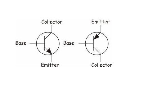
The Symbol for Bipolar Junction Transistor
The symbolic representations of both the N-P-N and P-N-P transistors are as follows

The only difference between P-N-P and the N-P-N transistors are that the movement of the current based on which the arrows are indicated.
Working Principle of BJT
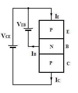
The three terminals present in the BJT are responsible for the formation of the junctions of the emitter and the base as well as a collector and the base. As considered the junction of base and the emitter is in the forward bias and the collector-base junction is in revere bias. Because of the forward biasing at the base and the emitter the flow of the majority carriers takes place from the emitter to the base.
As the region at the base is of light doping concentration, not all the majority carriers combine some of them tends to flow towards the collector. In this way, the currents at the emitter, base, and the collector are generated. The emitter current generated is the sum of the base and the collector currents. The amount of generated base current is less compared to that of the currents generated at the emitter and the collector.
The working principle remains the same for both P-N-P and the N-P-N transistor but the only difference between them is there majority charge carriers. In P-N-P the majority of the carriers are holes and in N-P-N the majority of the carriers are the electrons.
Equivalent Circuit of BJT
As the discussion of transistors makes it very clear that the formation of the transistor is due to the involvement of the two diodes connected back to the back of it. Hence these diodes lead to the formation of the two respective junctions which further relates to the presence of terminals in it.

P-N-P Transistor Equivalent Circuit Representation (BJT)
Hence the circuit of BJT can be represented by the two diodes with the junction P-N. This represents the equivalent circuit of BJT.
Bipolar Junction Transistor Biasing
The biasing of the bipolar junction transistor is nothing but the application of the external supply of the voltages to the respective junctions involved in it. This biasing leads to the major process of the transistor based on which the regions are classified.
(1) Cut-off region
As both the junctions of the transistors are not supplied with any external supply. Hence there is no evident supply of the voltages seen. The region formed is defined as the cut-off region.
(2) Active region
In this, the one junction must be kept in the mode of forwarding bias the other will be at the reverse bias. This type of region is referred to as the active region. In this, the q-point will be at the center of the characteristics curve so that it is most frequently used during the operations.
(3) Saturation region
In this both the junctions must be at the forward mode that is on highly conducting mode. This type of region is referred to as the saturation region.
During the application of the transistor as a switch, the cut-off mode and the saturation modes are preferred. That is either it should function in completely ON mode or the OFF mode. Hence this Q-point concept in the active region and in the other modes in order to make it stable there is the requirement of the biasing.
(1) Fixed Bias
This bias is also referred to as the base bias. In this type of bias, the connection of the single power supply will be maintained between the base and the collector with the help of the two resistors. If the values of the resistance are varied based on it the current at the terminal base can be adjusted. In this way, the Q-point can also be monitored.
(2) Collector-Base Bias
In this, the resistor of the base is collected across the collector rather than connecting it to the supply. This type of bias is preferred during the stabilization of the Q-point against the temperature changes.
If the collector current tends to increase there can be the voltage drop at the resistor resulting in the reduction of the value of the voltage across the resistor of the base. In this way, the current at the base gets reduced simultaneously the current value at the collector is reduced. This will reduce the effect of the temperature on the Q-point by making it stable
(3) Self-Bias
This type of bias is also referred to as the voltage divider bias. This type of bias is the most frequently used. The resistors arranged in the form of potential divider circuitry. Hence the equal or the fixed amounts of the voltages are supplied to the base terminal. In this way, the biasing techniques for the transistors are classified.
Bipolar Junction Transistor Characteristics
The characteristics of the BJT depends upon the configurations of it are classified whether it is of the common emitter, common base, and the common collector.
In this way, the characteristics for the various configurations of the bipolar junction transistor are compared.
Voltage Gain
The voltage gain is defined as the ratio between the output voltages to the applied input voltage. This voltage gain depends on the currents generated based on its configurations and the resistors connected across it.
Current Gain
The ratio of the currents generated at the output to the input value of the current referred to as the current gain of the particular transistor. The highest current gain is obtained at the common collector the configuration. With the very lesser voltage gain value, the highest current gains are obtained in the common collector configuration.
Applications of BJT
The applications of the bipolar junction transistor are as follows:
1) These are the transistors that are preferred in the logic circuits.
2) It is used in the circuits of amplification.
3) These are preferred in the oscillation circuits.
4) These are preferred in the multi-vibrator circuits.
5) In the clipping circuits, these are preferred for wave shaping circuits.
6) It used in the circuits of the timer and the circuits of the time delay.
7) These are used in the circuits of switching.
8) Used in the circuits of detector or as demodulation.
Hope you have understood how a transistor works let see how should we select these transistors before using them in our circuits. For that please refer to this for How to Select a Transistor.
Please refer to this link to know more about Transistor Transistor Logic MCQs, Transistor Biasing MCQs.
Please refer to this link to know more about BJT Amplifier
These bipolar junction transistors are constructed in a simpler manner. These are considered as the basic classification of the transistors. The basic application of this transistor is evident frequently as the switches. The reason behind this is that its design is less complex compared to other transistors.
Now can you define why the configurations in the BJT are classified and the importance of it in the electronic systems?