In safety equipment, flame sensors, fire alarms, and smoke sensors play a major role because these sensors assist us in maintaining our offices, homes, or stores very safe from fire accidents. Generally, safety equipment is used in almost all apartments, modern homes, cinema halls, offices, and shopping malls, and in some regions, it is compulsory to fire security devices. To overcome this problem, a flame sensor is used to protect all these from fires or flames. This article discusses an overview of a flame sensor – working with applications.
What is a Flame Sensor?
A flame sensor definition is a type of detector that is used to detect as well as react to the occurrence of a fire or flame. A flame sensor frequently responds faster & more precisely as compared to a heat or smoke sensor because of the mechanisms it utilizes to notice the flame. Flame sensors are usually used to verify whether the furnaces are functioning correctly. These sensors are also used in an ignition system to get precise actions otherwise to inform the operator.
Flame Sensor Working Principle
Flame sensors use UV (Ultraviolet) or IR (Infra-Red) or UV-IR technology to identify flames below a second. These sensors react to a detected flame based on the installation, although it includes sounding an alarm, disabling a fuel line & activating a fire control system.
The flame sensor with UV technology works by simply sensing the UV radiation. Generally, all fires generate UV radiation at the ignition point so, in case of a fire, the sensor would become alert of it & generate a series of pulses that are changed by detector electronics and gives an alarm output.
The flame sensor with IR technology works by checking the IR spectral band for particular ornamentation that hot gases emit. But, this kind of device needs a flickering movement of the flame. Generally, infrared radiation is not only generated by flames but also radiated from lamps, ovens, etc. So, there is a high risk of a fake alarm
The sensor with UV-IR is capable of detecting both UV & IR radiations, thus it possesses both sensors. The combined sensor has a better rejection capacity for false alarms as compared to a separate UV/IR detector.
Flame Sensor Types
There are different types of flame sensors like ultraviolet, infrared, Ultraviolet, Multi-Spectrum Infrared, IR3 flame,
UV Flame Sensors
UV frame or ultraviolet frame sensors are used to detect ultraviolet radiation because most fires emit ultraviolet radiation. These sensors are particularly helpful for services that are prone to particular hazards like halogen, metal fires & hydrocarbon. So, these types of sensors provide great sensitivity at small distances approximately 0 to 50 feet but, their performance will decrease at any length. These sensors respond to electrical discharges such as lightning.
Infrared Flame Sensors
Infrared flame sensors monitor IR radiation. These sensors also detect & analyze the IR spectral band to discover particular predefined prototypes given off through hot gases. These prototypes are detected with thermal imaging or thermographic cameras. The technology used by these sensors is flame recognition technology which detects the near-infrared radiation with a Charge-coupled device (CCD). The IR radiation sensors will affect significantly by the vapor of water as water simply absorbs a main part of the received infrared radiation. Because of this main reason, these sensors are not able to provide precise results in an outside environment.
Ultraviolet/Infrared Flame Detectors
Ultraviolet/infrared flame detectors add sensors for both UV & IR radiation. These two sensors simply work separately. But, some included circuitry & wiring to assist the detector procedure & evaluate both UV and IR signals. So this helps dispel any fake alarms that a single signal or the other may provoke.
This improved immunity to fake alarms permits ultraviolet or infrared flame detectors to be utilized in both indoor as well as outdoor applications. But, it limits fire detection to comprise fires that simply produce both UV & IR radiation.
Multi-Spectrum Infrared Flame Detectors
MSIR sensors utilize many IR wavelengths to differentiate flame-producing radiation from the sources of non-flame-production radiation. MSIR sensors respond to fires very quickly up to a distance of 200 feet both indoors & outdoors. These sensors are capable of detecting flames even between the smokiest of fires and also not causes fake alarms because of sunlight, lighting, otherwise other hot objects within the surrounding area.
IR3 Flame Detector
IR3 flame sensors compare the emission patterns among three various infrared spectral bands & the radiation bands ratio. Usually, these types of flame sensors are programmed to notice one radiation band in the 4.4-micrometer range & the remaining two bands range below & above the 4.4-micrometer spectrum. So this sensor is capable of separating the actual flames & the non-flame radiations that affect the results. Thus, these sensors provide superior flame detection results by simply avoiding the background radiations.
Apart from the visible, UV, IR & IR3 flame sensors, different other sensors are also found such as IR/IR flame detectors, 3IR+UV flame detectors, IR thermal cameras & UV/IR flame detectors.
Flame Sensor Arduino
The flame sensor interfacing with a microcontroller like an Arduino is shown below. Here, the flame sensor used is an Infrared flame sensor.
This sensor is available in small size and is used to detect a source of fire or any other clear light source. Basically, this kind of sensor detects infrared light with 760 nm to 1100 nm range wavelength that is generated from the light source or fire or flame. This IR flame sensor includes a YG1006 Phototransistor sensor which has high sensitivity & high speed.
Infrared sensor modules are available in two types where one type includes three pins and the other type includes four pins. The main difference between these two modules is; the three-pin module provides only digital output whereas four pin module provides both analog and digital outputs. So, these two modules can be used easily with different microcontroller boards. Here there pin flame sensor is used in this interfacing.
This 3-pin flame sensor module includes different components like phototransistor, trimpot, LM393, power LED and output LED.
Flame Sensor Pin Diagram
The three-pin flame sensor pin diagram is shown below.
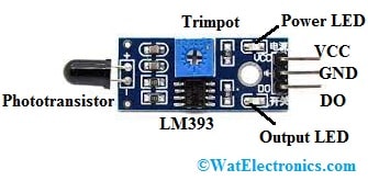
Flame Sensor Module
- Pin1 (VCC): This is a 5V power supply pin.
- Pin2 (GND): This is a GND pin.
- Pin3 (OUT): This is a digital output pin.
Specifications
The specifications of the flame sensor include the following.
- The range of operating voltage ranges from 3.3V to 5V.
- The operating current is 15 mA.
- The comparator chip used is LM393.
- The type of sensor is YG1006 Photo Transistor.
- Sensitivity can be adjusted by a potentiometer.
- The output type is Digital o/p or Digital & Analog output.
- Red LED is for power and green LED is for output.
- The range of the spectrum is from 760nm to 1100nm
- The detection angle is from 0 to 60 degrees.
- Operating temperature ranges from -25℃ to 85℃.
- The size of PCB is 3cm X 1.6cm.
YG1006 Phototransistor
In flame sensor, YG1006 Phototransistor is an NPN type Transistor that is coated with black epoxy to make it responsive to IR radiation. Although, this transistor from the outside looks like a 2-terminal block LED. The main function of this transistor is to detect light between 760 nm to 1100 nm wavelength range. This transistor includes two terminals where a longer terminal works like an emitter and a shorter terminal works like the collector and it doesn’t include a base terminal similar to the normal transistor. Once it detects flame then current flows in between emitter & collector terminals.
Trim pot
The trimpot is also called a variable resistor with a preset knob and this knob is rotated to control the sensitivity of fire detection. If this knob is turned in a clockwise direction, then the sensor’s sensitivity will be enhanced. Similarly, if it is turned in anticlockwise then the Flame sensor’s sensitivity will be reduced.
Power LED
The function of the Power LED in this sensor is to indicate the sensor’s power supply is turned ON/OFF. Once we connect the power supply to the sensor, the LED will be activated.
Output LED
Once the flame sensor detects the flame then the Red color LED will be turned ON. Once it does not notice any flame then this LED will be deactivated.
Flame Sensor Circuit Diagram
The circuit diagram of the flame sensor is shown below. This sensor module circuit can be designed with different components like LM393, YG1006 Phototransistor, two 1K Resistors like R1& R3, R2 -10K Resistor, VR1 – 10K Potentiometer, two 0.1 uF C1, C2 Ceramic Capacitors & D1, D2 RED LEDs.

Flame Sensor Circuit Diagram
Working
Initially, we have to connect this sensor module circuit to the 5v power supply. After that, the threshold voltage needs to be set at the Non-Inverting terminal of the IC based on the nonexistence of flame by simply turning the knob to set the sensitivity of the sensor.
Once this sensor detects any flame or fire in the 760 nm to 1100 nm wavelength range then the Phototransistor’s resistance will decrease. After that, the highest amount of voltage will be allocated across the R2 resistor. As a result, from the Phototransistor, less amount of voltage will provide to the Inverting terminal of the IC. After that, this IC evaluates this voltage by the threshold voltage. So, in this situation, the i/p voltage is below as compared to the threshold voltage, thus the output of the sensor goes LOW.
Similarly, once this sensor module does not notice any flame or fire then the transistor’s resistance will be high. After that, the highest amount of voltage will be allotted across this Phototransistor. Thus from the Phototransistor, the maximum amount of voltage is provided to the Inverting terminal of the IC. After that, the IC in the module will evaluate this voltage by the threshold voltage. So in this state, this i/p voltage is higher as compared to the threshold voltage, as a result, the o/p of the sensor goes High.
Interfacing Arduino Flame Sensor
The required components to interface this flame sensor with Arduino mainly include Arduino Uno, 5V buzzer, flame sensor, 2N2222 NPN Transistor, 1KΩ Resistor, 1N4007 Diode, mini breadboard, power supply, and connecting wires.
This sensor includes three pins like VCC, GND & DO as discussed above. The connection of this module with Arduino follows; Connect VCC & GND pins to +5V and GND of the power supply. The Digital Output ‘D0’ pin is connected to Arduino’s 11th pin. Here, a buzzer is used to specify the detection of a fire or flame. The Buzzer circuit includes an NPN Transistor, 1KΩ Resistor, a PN Junction Diode & a 5V Buzzer. The 12-pin of Arduino UNO like Digital I/O drives the buzzer.
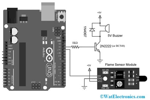
Flame Sensor Interfacing with Arduino Uno
Code
The code for Arduino flame sensor is shown below.
const int buzzerPin = 12;
const int flamePin = 11;
int Flame = HIGH;
void setup()
{
pinMode(buzzerPin, OUTPUT);
pinMode(flamePin, INPUT);
Serial.begin(9600);
}
void loop()
{
Flame = digitalRead(flamePin);
if (Flame== LOW)
{
Serial.println(“Fire!!!”);
digitalWrite(buzzerPin, HIGH);
}
else
{
Serial.println(“No worries”);
digitalWrite(buzzerPin, LOW);
}
}
Once the connections are made, the Arduino Uno code needs to be uploaded. To check this sensor’s functionality, a field lighter needs to be placed near the sensor. In normal situations, the sensor’s output is HIGH. Once the flame sensor detects any flame, then its output will become LOW. Here, the Arduino Uno board detects this LOW signal on its i/p pin & turns ON the Buzzer.
Advantages and Disadvantages
The advantages of the flame sensors include the following.
- These sensors have High-speed response.
- These sensors are resistant to fake alarms.
- This sensor frequently & more accurately respond faster as compared to a heat or smoke sensor because of the mechanisms it utilizes for detecting the flame.
- It has a long detection distance, environmental adaptability is good & high reliability.
- This sensor lasts for about 5 years and the average lifetime of a heating system is 15 – 30 years.
The disadvantages of the flame sensor include the following.
- The UV or IR flame detectors cannot be applicable for non-carbon fires & capable of detecting fires that produce both the UV and IR radiation not separately.
- The optical flame sensor price is high.
Applications
The flame sensor applications include the following.
- A flame-sensor is mainly used to detect & react to the occurrence of a flame/fire.
- Flame sensors are used in fire alarms, fire detection, drying systems, fire fighting robot, industrial heating, hydrogen stations, domestic heating systems, industrial gas turbines, gas-powered cooking devices, etc.
- These are used in MDF factories, pharmaceuticals, fume cupboards, coal handling, spray booths, nuclear industry, fabrication of metal, clothing dryers, aircraft hangars, gas fuelled cookers, domestic heating systems, heating & drying systems in industries, generators & storage tanks.
Know more about Pulse Sensor, Door Sensor.
Thus, this is all about flame sensor – working and its interfacing with controllers. This sensor is used for detecting the existence of a fire source otherwise any other bright source of light. Here is a question for you, what is a temperature sensor?