RFID and NFC are wireless technologies that have become very popular for asset & inventory tracking. These technologies can be adopted by different Industries like trucking, oil & mining, warehousing, shipping, and logistics as elements of their digital conversion efforts. The PN532 is a highly integrated NFC controller IC capable of supporting NFC, RFID reader, RFID writer, card emulation, and peer-to-peer communication and RFID technologies to communicate data over distance. Thus, NFC is a subset of RFID that uses 13.56 MHz high frequency to allow communication between two devices whenever they are very close to each other.
NFC devices function as both a reader and a tag, which will enable two-way communication, and are commonly used in wearable devices, smartphones, and access cards. Thus, RFID utilizes radio waves to broadcast data where its range is: LF RFID is 10 cm, HF RFID is 10–30 cm, UHF RFID is 3–15 m, and Active RFID is 100 m+. NFC RFID modules are frequently used to replace barcodes within wireless communication systems. This article elaborates on the PN532 NFC RFID module, its working, and its applications.
What is the PN532 NFC RFID Module?
The PN532 NFC RFID transmission module by NXP is a highly integrated transmission module used for contactless communication at 13.56 MHz. It integrates an embedded 80C51-compatible microcontroller core that executes NFC firmware. Thus, the PN532 module combines a modulation & demodulation concept for different types of contactless communication methods and protocols with simple-to-use firmware for the various modes and host controller interfaces. Thus, the PN532 NFC RFID module works like an RFID reader, writer, virtual card, or 1443-A card and supports NFC through Android phones. This module can also be compatible with Arduino.
Working
The PN532 NFC RFID transmission module works by enabling contactless communication at 13.56 MHz. Thus, this module uses an in-built antenna to communicate with cards & tags that can also include chips and antennas. Thus, whenever a card is brought near the module, the chip within the card receives power, and the module communicates with it.
The PN532 NFC RFID module includes a mode switch that lets you switch between SPI, I2C & UART modes. Thus, this module can also be compatible with Arduino and supports NFC on Android phones. So the typical communication distance for this module is 3–7 cm depending on antenna size, tag type, and power level.
Pin Configuration:
PN532 NFC RFID module pin configuration is shown below. This module includes twelve pins, which are explained below.
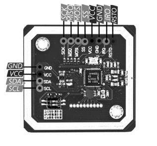
PN532 NFC RFID Module Pin Configuration
- Pin (VCC): This pin provides a power supply to the whole module.
- Pin (GND): It is the ground pin of the module.
- Pin (TXD): This TXD pin is used to transmit the data.
- Pin (RXD): This RXD pin is used to receive the data.
- Pin (SDA): It is a serial data pin used for I2C communication.
- Pin (SCL): It is a serial CLK pin; it is used to transmit data between devices based on the CLK pulse.
- Pin (IRQ): It is an interrupt pin; thus, it is used to generate the interrupt to I2C communication to obtain the attention of the Microcontroller/Arduino.
- Pin (RST): It is a reset pin of a module; it helps in resetting the device through an external signal.
- Pin (MOSI): It is a Master Out Slave In pin of a module, thus it helps to send data to PN532 from Arduino.
- Pin (MISO): It is a Master-Slave Out pin of a module; thus, it helps to transmit data to Arduino from PN532.
- Pin (SS): It is a slave select pin of the module; it triggers the SPI communication of the Slave (PN532).
- Pin (SCK): It’s a CLK pin of a module; it helps in the transceiving of data based on the CLK pulse.
Features & Specifications:
The features and specifications of the PN532 NFC RFID module include the following.
- PN532 NFC RFID is a transmission module
- It has an 80C51 microcontroller core including 1 Kbyte RAM and 40 Kbyte ROM.
- It has extremely incorporated analog circuitry to decode & demodulate responses.
- Integrated RF level detector
- Integrated data mode detector
- It is built with a PCB Antenna with a communication distance of 3–7 cm.
- It supports MIFIRE higher transmit speed communication at 424 Kbits/s & 212Kbits/s.
- This module supports the I2C interface, high-speed serial UART & SPI interface.
- It has a flexible interrupt with an IRQ pin.
- Hard reset through the low power function.
- Power down mode for each embedded firmware
- Its operating voltage ranges from +2.7V to +5.5V.
- It can work as an RFID reader & writer, an RFID card, or a virtual card.
- Operating temperature ranges from -30ºC to +85ºC.
- Automatic wake-up on SPI interfaces, HSU & I2C whenever the device is in the power-down mode.
- It has a programmable timer.
- Its low-power modes include 1 µA Hard-Power-Down mode and 22 µA soft-power-down mode.
- Contactless communication is possible at 13.56MHz.
- Its onboard level shifter is standard 5V TTL used for UART and I2C, and 3.3V TTL SPI.
- Its buffered output drivers are used to connect an antenna with fewer external components.
Equivalent & Alternatives :
Equivalent PN532 NFC RFID modules are; RC522, EM-18, RMD6300, etc. Alternative NFC RFID modules are; TRF7970A, MSP430G2xx, ARRSN5-868.000MHZ, M7E-PICO, RI-SMD-MRD2, DLP-RFID2, ARRUN5-915.000MHZ, M7E-DEKA, RI-STU-MRD2, ARRUN5-868.000MHZ, M7E-PICO-CB, DLP-RFID1-OG, etc.
PN532 NFC RFID Module Architecture
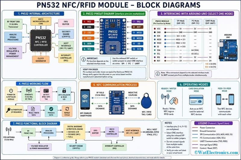
The internal architecture of the PN532 NFC RFID module is designed to simplify contactless communication while supporting multiple RFID and NFC standards. Unlike a basic RFID reader, the PN532 integrates an embedded microcontroller, RF front-end circuitry, communication interfaces, and hardware security features within a single chip. This high level of integration reduces the need for external components and allows developers to easily implement NFC-based applications.
PN532 NFC RFID Module Architecture Diagram
The major functional blocks within the PN532 include:
RF Front-End: Generates the 13.56 MHz electromagnetic field and detects the response from NFC tags or RFID cards.
80C51 Embedded Microcontroller: Executes the firmware responsible for NFC protocols, communication management, and command processing.
Host Communication Interface: Provides SPI, I2C, and UART interfaces for communication with external microcontrollers.
FIFO Buffer: Temporarily stores incoming and outgoing data to improve communication efficiency.
Security Engine: Supports hardware-based encryption and authentication used by MIFARE cards.
Power Management Unit: Controls low-power operating modes to minimize energy consumption.
This integrated architecture enables the PN532 to operate as an NFC reader, RFID writer, peer-to-peer communication device, or card emulator.
Supported RFID and NFC Standards
One of the major advantages of the PN532 module is its compatibility with multiple international RFID and NFC communication standards. This broad compatibility allows the module to communicate with a wide range of contactless smart cards, NFC-enabled smartphones, and RFID tags.
The PN532 supports the following standards:
| Standard | Description |
| ISO/IEC 14443 Type A | Used in MIFARE Classic, Ultralight, NTAG series |
| ISO/IEC 14443 Type B | Used in electronic passports and secure identification systems |
| ISO/IEC 18092 | NFC Peer-to-Peer communication |
| FeliCa (JIS X 6319-4) | Used mainly in Japan for transportation and payment systems |
| MIFARE Classic | Popular access control and attendance cards |
| MIFARE | Popular access control and attendance cards |
| NFC Forum Tag Types | Supports Type 1, Type 2, Type 3, and Type 4 NFC tags |
Because of this extensive compatibility, the PN532 is widely used in industrial automation, smart cards, mobile payments, IoT devices, and access control systems.
PN532 NFC RFID Module Interfacing with Arduino Board
The PN532 NFC RFID module interfacing with the Arduino Uno Board is shown below. This interfacing is a great technique to include a new measurement in your projects. The PN532 NFC RFID module can read & write to RFID tags as well as cards to make it a flexible tool, it is used in applications like inventory management, access control systems, contactless payments, etc.
Thus, the required components for this interfacing mainly include; Arduino UNO, PN532 NFC RFID module, breadboard, and jumper wires. The connections of this interfacing follow as;
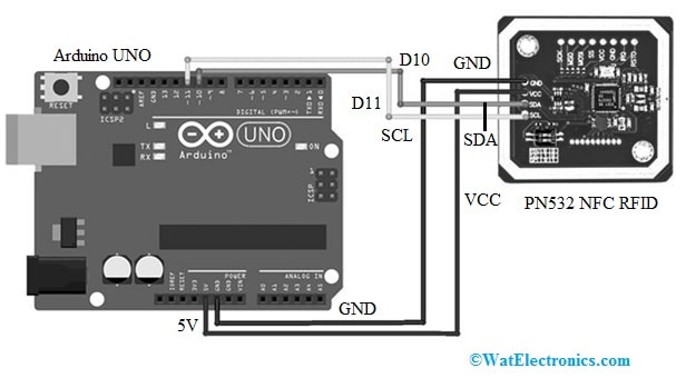
PN532 NFC RFID Module Interfacing with Arduino Uno
- The 5V pin of the Arduino board is connected to the VCC pin of the PN532 NFC module.
- The GND pin of the Arduino board is connected to the GND pin of the PN532 NFC module.
- The Arduino board’s D10 pin is connected to the SDA pin of the PN532 NFC module.
- The Arduino board’s D11 pin is connected to the SCL pin of the PN532 NFC module.
Code
The required code for the PN532 NFC RFID module interfacing with the Arduino board is shown below.
#include <SoftwareSerial.h>
<PN532_SWHSU.h>
<PN532.h>
SoftwareSerial SWSerial( 10, 11 ); // RX, TX
PN532_SWHSU pn532swhsu( SWSerial );
PN532 nfc( pn532swhsu );
void setup(void) {
Serial.begin(115200);
Serial.println(“Hello Maker!”);
nfc.begin();
uint32_t versiondata = nfc.getFirmwareVersion();
if (! versiondata) {
Serial.print(“Didn’t Find PN53x Module”);
while (1); // Halt
}
// Got valid data, print it out!
Serial.print(“Found chip PN5”); Serial.println((versiondata>>24) & 0xFF, HEX);
Serial.print(“Firmware ver. “); Serial.print((versiondata>>16) & 0xFF, DEC);
Serial.print(‘.’); Serial.println((versiondata>>8) & 0xFF, DEC);
// Configure board to read RFID tags
nfc.SAMConfig();
Serial.println(“Waiting for an ISO14443A Card …”);
}
void loop(void) {
boolean success;
uint8_t uid[] = { 0, 0, 0, 0, 0, 0, 0 }; // Buffer to store the returned UI
uint8_t uidLength; // Length of the UID (4 or 7 bytes depending on ISO14443A card type)
success = nfc.readPassiveTargetID(PN532_MIFARE_ISO14443A, &uid[0], &uidLength);
if (success) {
Serial.println(“Found A Card!”);
Serial.print(“UID Length: “);Serial.print(uidLength, DEC);Serial.println(” bytes”);
Serial.print(“UID Value: “);
for (uint8_t i=0; i < uidLength; i++)
{
Serial.print(” 0x”);Serial.print(uid[i], HEX);
}
Serial.println(“”);
// 2 second halt
delay(2000);
}
else
{
// PN532 probably timed out waiting for a card
Serial.println(“Timed out! Waiting for a card…”);
}
}
Working
Once the above code is uploaded, the circuit needs to be tested. The Arduino board starts working once it gets a power supply. So this code causes the Arduino board to read accordingly from the sensor.
The code includes different libraries, where the SoftwareSerial library is used for serial communication on the Arduino board, and the PN532_SWHSU library is used for the PN532 module & provides a function to communicate with it. Thus, finally, the PN532 library includes general functions used for interacting with the module.
In the above code, the void setup() function initializes serial communication at a 115200 baud rate and prints the message on the serial monitor to initialize the PN532 module. So that it checks if it is connected properly, then it prints out the type of chip & firmware version. After that, it arranges the board for reading RFID tags by simply calling the function of nfc.SAMConfig().Thus, the void loop() function in the above code tries to read a passive target ID with the nfc.readPassiveTargetID() function.
Thus, if any card is found, then it prints the value and length of the unique identifier of the card on the serial monitor. Likewise, if any card is not found, then it prints a Waiting message for a card like Timed out on the serial monitor. Thus, the code waits for two seconds before it attempts to read another card. Thus, this interfacing can be used in mobile phones, door keys, car keys, security systems, etc.
Operating Modes of the PN532 NFC RFID Module
The PN532 module supports three primary operating modes, making it much more versatile than conventional RFID readers.
Reader/Writer Mode
In Reader/Writer mode, the PN532 generates a 13.56 MHz RF field that powers passive RFID tags or NFC cards. After detecting a nearby tag, it reads or writes data stored in the tag’s memory.
Typical applications include:
- Attendance systems
- Asset tracking
- Library management
- Warehouse inventory
- Smart identification cards
Card Emulation Mode
In Card Emulation mode, the PN532 behaves like an RFID or NFC card instead of a reader. External NFC devices, such as smartphones or payment terminals, detect the PN532 as if it were a physical NFC card.
Applications include:
- Electronic ticketing
- Smart identity cards
- Secure authentication
- Mobile payment testing
- Access control
Peer-to-Peer Mode
Peer-to-Peer mode enables two NFC-enabled devices to exchange data directly without requiring a central server.
Typical examples include:
- Smartphone-to-smartphone communication
- File sharing
- Contact information exchange
- Device pairing
- Bluetooth setup
How does the PN532 detect an RFID Tag?
The PN532 detects RFID tags using electromagnetic induction and load modulation techniques. Initially, the module generates a continuous 13.56 MHz radio frequency field through its onboard antenna. When a passive RFID card enters this field, the antenna coil inside the card receives sufficient energy to power the embedded integrated circuit.
Once powered, the RFID tag modulates the electromagnetic field by slightly varying its electrical load. These small variations are detected by the PN532 receiver circuitry, which demodulates the received signal into digital data.
After detecting a valid response, the PN532 performs an anti-collision algorithm to identify multiple cards if more than one tag is present. It then retrieves the Unique Identifier (UID) of the selected card and establishes communication for reading or writing data. This entire detection process occurs within a few milliseconds.
RFID Authentication Process
Before accessing protected memory blocks on RFID cards such as MIFARE Classic cards, the PN532 performs an authentication process.
The authentication sequence consists of the following steps:
- Detect the RFID card.
- Read the card’s Unique Identifier (UID).
- Select the desired memory sector.
- Send the authentication command.
- Provide Key A or Key B for authentication.
- Verify the authentication response.
- Read or write the requested data block.
If authentication fails, the module denies access to the protected memory area. This mechanism provides additional security against unauthorized access.
Communication Interfaces of the PN532 Module
The PN532 supports three different communication interfaces, allowing it to connect with almost any microcontroller platform.
SPI Interface
The SPI interface offers the highest communication speed and is commonly used in Arduino and STM32 projects.
Advantages:
- High-speed communication
- Low latency
- Reliable data transfer
Typical pins include:
- MOSI
- MISO
- SCK
- SS
I2C Interface
The I2C interface uses only two communication lines and is ideal when multiple sensors share the same bus.
Advantages:
- Requires fewer wires
- Supports multiple slave devices
- Simple hardware implementation
Typical pins include:
- SDA
- SCL
UART Interface
UART communication provides simple serial communication between the PN532 and the host controller.
Advantages:
- Easy debugging
- Long-distance communication compared to SPI
- Widely supported
Pins:
- TX
- RX
Power Management Features
The PN532 incorporates several power-saving mechanisms suitable for battery-operated embedded systems. The available operating modes include:
Normal Mode
All communication interfaces remain active, allowing continuous RFID and NFC communication.
Soft Power-Down Mode
The processor enters a low-power sleep state while retaining configuration settings.
Current consumption: Approximately 22 µA.
Hard Power-Down Mode
Almost all internal circuitry is disabled.
Current consumption: Approximately 1 µA.
Automatic Wake-Up
The PN532 can automatically wake from low-power mode whenever activity is detected on the SPI, UART, or I2C communication interface. These power-saving features make the module suitable for portable electronic devices.
Memory Structure of MIFARE Classic Cards
Many RFID cards used with the PN532 are based on the MIFARE Classic architecture. The memory is organized into sectors and blocks.
A typical 1 KB MIFARE card consists of:
- 16 sectors
- 4 blocks per sector
- 16 bytes per block
Each sector contains:
- Data blocks
- Sector trailer
- Access bits
- Authentication keys
The sector trailer stores Key A, Key B, and access control information that determines whether memory can be read or modified. Understanding this memory organization is important when developing RFID applications involving secure data storage.
Troubleshooting PN532 NFC RFID Module
While interfacing the PN532 with Arduino or other microcontrollers, several common issues may occur. The following table lists common problems along with their possible causes and solutions.
| Problem | Possible Cause Solution |
| Module not detected | Incorrect wiring. Verify all power and communication connections |
| Unable to read RFID tag | Tag not supported. Check that the card uses ISO14443A or another supported protocol |
| Firmware version not displayed | Communication interface incorrectly configured. Verify SPI, I2C, or UART mode selection |
| Random communication errors | Loose jumper wires: Ensure secure wiring and proper grounding |
| Card detected intermittently | Tag too far from the antenna. Place the tag within 3–7 cm of the antenna |
| Arduino compilation errors | Missing PN532 library. Install the required PN532 library in the Arduino IDE |
| Authentication failed | Incorrect Key A or Key B: Use the correct authentication keys for the selected sector |
| Slow communication | Wrong baud rate or interface settings. Verify the configured communication parameters |
Difference between NFC and RFID
The NFC Vs RFID includes the following.
| NFC |
RFID |
| NFC is a near-field communication, | RFID is radio frequency identification. |
| Its communication range is limited from 0 to 5 cm. | It can communicate over up to 100 meters. |
| It operates in the 13.56 MHz single-frequency band. | This module uses various frequency bands. |
| NFC uses one-way or two-way communication. | RFID uses one-way communication only. |
| The NFC data transfer rate is 424 kbps. | It has different rates based on frequency. |
| Its storage space is more. | It has less storage space. |
| These are not expensive. | RFID readers are expensive due to longer range & bulk scanning systems. |
| It stores more complex data. | It stores simpler data like; number identification. |
| NFC communication devices are peer-to-peer. | RFID communication devices are master-slave. |
| It is frequently used for safety communication between consumer devices like smartphones, mainly for mobile payment and access control. | It is used frequently for asset management, vehicle access control, logistics, and production. |
PN532 vs RC522 RFID Module
Both the PN532 and RC522 are widely used RFID modules; however, the PN532 offers significantly more features.
| Feature | PN532 | RC522 |
| NFC Support | Yes | No |
| RFID Reader | Yes | Yes |
| RFID Writer | Yes | Limited |
| Card Emulation | Yes | No |
| Peer-to-Peer Communication | Yes | No |
| Smartphone Compatibility | Yes | No |
| Communication Interfaces | SPI, I2C, UART | SPI |
| Supported Standards | ISO14443A/B, FeliCa | NFC Mainly MIFARE |
| Operating Voltage | 2.7–5.5 V | 3.3 V |
| Typical Applications | Mobile payments, NFC, IoT | Access control, attendance systems |
Advantages
The advantages of the PN532 NFC RFID module include the following.
- This module supports different protocols with Arduino to communicate, such as SPI, I2C, or UART.
- This module uses multiple communication modes like HSU, SPI & I2C to switch easily between these modes with a small onboard switch.
- This module is small and very simple to use in your project.
- It is compatible with an Arduino board and can be connected and played through a shield.
- It supports NFC through Android phones.
- The PN532 module includes a temperature sensor that stops RF transmission automatically whenever the temperature of the chip is very high.
- Its unique feature can turn off the inside antenna driver to disable the RF field.
- It supports RFID reading & writing so that it can read & write to tags & cards to communicate through phones.
- This module supports ISO/IEC 14443-4, Mifare, FeliCa cards & Innovision Jewel.
Disadvantages
The disadvantages of the PN532 NFC RFID module include the following.
- Some NFC RFID modules may not work.
- Whenever RFID & NFC cards are close together, they can interfere with each other, by preventing them from functioning.
- For some data block read commands, you may need to issue the Read_FIFO command several times to move bytes to the receive buffer from the FIFO.
- After getting the command results within the receive buffer, you have to execute a scan procedure to discover the specific bytes you require.
- Generally, error messages appear only if the tag is detached throughout an operation.
- If a software reset is noticed, then the software initialization code section will be skipped.
- Generally, NFC has a short range, not above 20 cm, which is the main drawback in tag scanning on a long line of products.
- RFID systems are expensive to implement as compared to barcode systems.
- NFC tags are more expensive than other types of RFID tags because of extra encryption costs.
Applications
The applications of the PN532 NFC RFID module include the following.
- The PN532 NFC RFID module can read & write to different kinds of RFID cards.
- These two modules communicate wirelessly with each other.
- It can be used with Android phones and allows mobile payments.
- This module can be used to include NFC abilities in Arduino projects.
- PN532 NFC RFID module can serve as a tool mainly for other communications within your smartphone.
- It can be embedded within modules to allow easy pairing through your Arduino projects.
- This module can read & write RFID cards.
Please refer to this link for the PN532 NFC RFID module datasheet.
Frequently Asked Questions (FAQs)
1. Can the PN532 read both NFC tags and RFID cards?
Yes. The PN532 supports both NFC tags and RFID cards that comply with supported communication standards such as ISO/IEC 14443 Type A, Type B, and FeliCa.
2. What is the maximum reading distance of the PN532?
The typical reading distance ranges from 3 cm to 7 cm, depending on the antenna size, tag type, and operating environment.
3. Can the PN532 write data to NFC tags?
Yes. The module can both read from and write data to supported NFC tags and RFID cards.
4. Does the PN532 support Android smartphones?
Yes. Most Android smartphones equipped with NFC can communicate with the PN532 for peer-to-peer communication, card emulation, or tag reading applications.
5. Which communication interface is the fastest?
SPI provides the highest communication speed, followed by UART and I²C.
6. Can multiple RFID cards be detected simultaneously?
Yes. The PN532 includes an anti-collision mechanism that can detect and identify multiple cards within its operating field before selecting one for communication.
7. Is the PN532 suitable for IoT projects?
Yes. Due to its multiple communication interfaces, low-power modes, and NFC capabilities, the PN532 is widely used in IoT, smart home, and industrial automation projects.
8. Can the PN532 emulate an NFC card?
Yes. In Card Emulation mode, the PN532 can behave like an NFC smart card, allowing communication with smartphones and NFC readers.
9. What is the operating frequency of the PN532?
The PN532 operates at the globally standardized 13.56 MHz frequency used for HF RFID and NFC communication.
10. Which microcontrollers are compatible with the PN532?
The PN532 can interface with a wide range of microcontrollers, including Arduino Uno, Arduino Mega, ESP32, ESP8266, STM32, Raspberry Pi, BeagleBone Black, PIC, AVR, MSP430, and ARM Cortex-M development boards through SPI, I²C, or UART interfaces.
Conclusion
The PN532 NFC RFID module is one of the most versatile and feature-rich NFC controllers available for embedded systems and IoT applications. Unlike conventional RFID reader modules, the PN532 supports multiple operating modes, including Reader/Writer Mode, Card Emulation Mode, and Peer-to-Peer Communication, making it suitable for a wide range of contactless communication applications. Its compatibility with multiple communication interfaces such as SPI, I²C, and UART, along with support for international standards like ISO/IEC 14443 Type A, Type B, FeliCa, and NFC protocols, allows it to interface seamlessly with popular development platforms including Arduino, ESP32, Raspberry Pi, STM32, and other microcontrollers.
The module’s integrated 80C51 microcontroller, low-power operating modes, built-in security features, and support for reading and writing RFID and NFC tags make it an excellent choice for both beginners and professional developers. Whether you are designing smart access control systems, attendance management solutions, mobile payment terminals, inventory tracking systems, contactless authentication devices, smart locks, healthcare applications, industrial automation systems, or IoT-enabled products, the PN532 provides a reliable, flexible, and easy-to-integrate solution.
With its excellent performance, broad protocol compatibility, and strong software support, the PN532 continues to be one of the most widely used NFC RFID modules for rapid prototyping, educational projects, and commercial embedded applications. By understanding its architecture, operating modes, communication interfaces, and practical implementation techniques, developers can build secure, efficient, and scalable contactless systems with minimal hardware complexity.
As NFC technology continues to expand into smart cities, digital identity, contactless payments, Industry 4.0, and connected IoT ecosystems, the PN532 remains a valuable development platform for creating next-generation wireless communication solutions. Whether your goal is to develop a simple RFID reader or a sophisticated NFC-enabled embedded system, the PN532 offers the flexibility and performance needed to transform innovative ideas into practical real-world applications.
Now that you understand how the PN532 NFC RFID module works, here’s a question to explore further: How does the PN532 compare with the RC522 RFID module in terms of communication protocols, performance, supported standards, and real-world applications?