The power transistor is a three-terminal device, composed of semiconductor materials. It is mainly designed for use in power supplies and high-power amplifiers. So, these transistors are suitable wherever high power, current & voltage are being used so that they handle high power and current in audio and switching circuits. The power transistor function is whenever a current or voltage is provided to one pair of the transistor terminals then it controls the current or voltage at the remaining pair of transistor terminals. These are also available in different types including different power ranges thus the examples of power transistors are; MJ15001, MJ15003, MJ15004, and many more. This article provides an overview of the MJ15004 transistor, pinout, specifications, and its applications.
What is MJ15004 Transistor?
The MJ15004 is a three-terminal PNP power transistor, designed for disk head positioners, high-power audio & other linear-type applications. This transistor handles 250 watts at 50Volts with a highly secure operating region and provides less distortion within complementary designs. Thus, these transistors have a 25-lowest current gain of at 5Amps of collector current and are suggested for their value and performance.
MJ15004 is a cutting-edge power transistor that is a perfect solution mainly for a wide range of applications including its advanced design & exceptional performance. So this transistor uses solid-state technology and provides improved durability and reliability as compared to other transistors thus, it can endure higher temperatures & work in harsh situations without changing its performance.
While looking for a suitable transistor for your application based on a few factors, it is very important to look into a few points on How to Select a Transistor.
Pin Configuration:
The MJ15004 transistor pin configuration is shown below. This transistor includes three terminals which are discussed below.
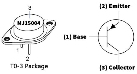
MJ15004 Transistor Pin Configuration
- Pin-1 (Base): This is the middle terminal of the transistor, denoted with ‘B’. This terminal is thin and lightly doped. The base terminal controls the collector-emitter current flow. A small base current allows a much larger current to flow between the collector and emitter.
- Pinp-2 (Emitter): The emitter terminal is denoted with ‘E’. It is medium-sized and doped strongly because the emitter injects majority charge carriers into the base region and is heavily doped to improve current conduction.
- Pin-3 (Collector): The collector region is designed to dissipate high power and withstand high voltage and current levels.
Features and Specifications:
The features and specifications of the MJ15004 transistor include the following.
- MJ15004 is a three-terminal power transistor.
- It is available in the TO3 package.
- Its polarity is PNP.
- The transistor material is Si.
- The mounting style is Through Hole.
- It has high secure operating region.
- It has a lower saturation voltage, thus resulting in decreased power loss & improved efficiency.
- It is a versatile transistor.
- It has a high DC gain.
- These transistors are RoHS-compliant and Pb−Free.
- Collector power dissipation or Pd maximum is 250 Watts at Tc = 25°C.
- Collector to base voltage or Vcb maximum is 140 Volts.
- Collector to emitter voltage or Vce maximum is 140 Volts.
- Max collector current or Ic max is 20Amps.
- The transition frequency or ft is 2 MHz.
- Collector capacitance or Cc is 1000 pF.
- Emitter to base voltage or |Veb| maximum is 5Volts.
- The forward current transfer ratio or hFE minimum is 25.
- Its minimum and maximum operating junction temperature range is -65°C to +150°C.
Specification Table
| Parameter | Value |
| Transistor Type | PNP |
| Package | TO-3 |
| VCEO | 140V |
| VCBO | 140V |
| VEBO | 5V |
| IC | 20A |
| Power Dissipation | 250W |
| hFE | 25 to 150 |
| ft | 2 MHz |
| Junction Temperature | 150°C |
Internal Structure
The internal structure of the MJ15004 transistor is shown below.
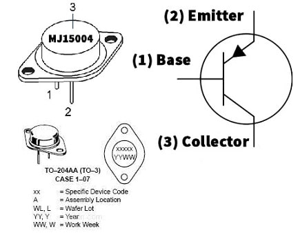
Internal Structure
PNP Silicon Structure
The MJ15004 high-power PNP Silicon Bipolar Junction Transistor. Its basic construction includes a very thin n-type semiconductor base region which is sandwiched between two heavily doped p-type semiconductor layers, like the emitter & the collector. This transistor is designed for high-power linear applications like disk head positioners & audio amplifiers.
Emitter Region
Pin-2 is the emitter region of the transistor, and this region is heavily doped with P-type material because the MJ15004 is a PNP-type transistor. Its main function is to “emit” charge carriers like holes into the base region. This region is designed to handle immense power, with a maximum continuous emitter current IE is 25 A, a maximum emitter-base voltage VEBO is 5V and an emitter cut-off current IEBO is 100 μA at VEB = 5 V.
Base Region
The “base” region of this transistor works as the control terminal, where small changes in current control a much larger electrical supply moving through the emitter and collector. Understanding the limitations of the base region is essential to avoid harm to the device.
Collector Region
Generally, the term “collector region” refers to how the hardware structure or operating boundaries of this terminal are defined. The collector region of the MJ15004 transistor works as the main “sink” that gets charge carriers from the emitter. So, it works as a large-area terminal designed to securely collect current, resist high voltages, and scatter heavy thermal loads.
Equivalent & Alternatives
Equivalent or alternate MJ15004 transistors are: 2N6609, MJ10000, MJ10002, and MJ10001, and the complementary MJ15004 PNP transistor is the MJ15003 NPN transistor.
Replacing a suitable transistor in any circuit based on requirement is very important. To know how to replace it, please refer to this; Replacing Transistors in Electronic Circuits: Factors and Considerations.
100Watts Audio Amplifier Circuit with Transistors
Audio amplifier is a significant component in sound systems that provide the required power supply to drive speakers and also deliver high-quality range sound output. The 100W audio amplifier circuit with transistors is shown below. So this circuit uses 2N3055 and MJ15004 transistors at the output section, and BD139, 2N3904, MPSA56, and MPSA06 transistors within the driver section & pre-amplifier section stand out mainly for their performance and reliability.
The required components to make this 100Watts audio amplifier circuit mainly include; Transistors like; 2N3055, MJ15004, MPSA06, MPSA56, BD139, and 2N3904. Resistors like; 15k, 560, 5.6k, 12k, 470, 30k, 1.2k, 10k, 100K,330K and 0.22. Capacitors like; 1uF, 47uF, 47pF and 0.1uF. Miscellaneous like; 1N5239D Zener Diode, 1N4148 Diodes, 0.53uH coil, and ±35V symmetrical power supply. So, connect the circuit as per the diagram illustrated below.
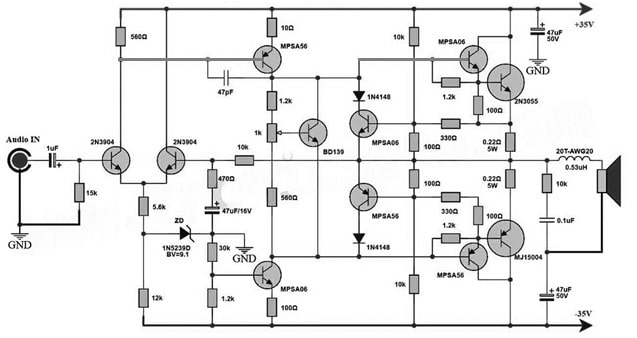
100Watts Audio Amplifier Circuit with Transistors
Working
The core of this 100Watts audio amplifier circuit mainly lies in its o/p stage, wherever the MJ15004 and 2N3055 transistors work to deliver strong power toward the speakers. So, the transistors in this stage are connected in such a way that to handle higher power loads while maintaining efficiency as well as stability. The MPSA56, MPSA06, 2N3904, and BD139 transistors serve as drivers, they control the current flow throughout the output transistors by ensuring the input signal’s accurate amplification.
The preamplifier section has MPSA56, MPSA06, BD139 & 2N3904 transistors which amplify the input signal before it attains the output stage. So this amplification procedure increases the signal to a certain level that is suitable to drive the output transistors, thus improving overall fidelity and performance.
Thus, the 100Watts audio amplifier circuit has 2N3055 and MJ15004 transistors in the output section, MPSA06, BD139, MPSA56 & 2N3904 transistors within the driver section & finally preamplifier sections present a consistent solution to amplify audio signals with precision and power. Thus, by controlling the abilities of every component and cautiously designing the layout of the circuit, this amplifier provides high-fidelity sound reproduction appropriate for a variety of audio applications. So, understanding this circuit design, allows enthusiasts to build and customize audio amplifier circuits to meet their precise requirements.
Connecting a base resistor to the base terminal of the transistor is mandatory to avoid it being damaged. So, please refer to this link for: Choosing Base Resistance for Transistors in Electronic Circuits.
Safe Operating Area (SOA)
The Safe Operating Area of the MJ15004 transistor can be described by the maximum limits of Collector Current and Collector-Emitter Voltage. So this transistor operates reliably without suffering secondary breakdown or thermal damage.
Simultaneous Voltage-Current Limits
The Simultaneous Voltage-Current Limits in an MJ15004 power transistor defines the Safe Operating Area (SOA). So this metric states that the transistor cannot manage its maximum rated voltage & its maximum rated current at the same time. In its place, when the operating voltage across the transistor increases, the allowable collector current severely reduces to avoid catastrophic failure.
Secondary Breakdown Protection
The Secondary Breakdown Protection in the context of the MJ15004 PNP power transistor refers to design features & strict operating guidelines. It is established to avoid a destructive, localized thermal-electrical failure identified as second breakdown.
Importance in Audio Amplifiers
The MJ15004 is a high-power & strong PNP bipolar junction transistor. Its main importance in audio amplification lies in its role in the complementary output stage. When it works next to its NPN counterpart, this transistor drives heavy speaker loads with durability & high fidelity.
Why the MJ15004 Transistor Became Popular among Amplifier Designers?
The MJ15004 PNP power transistor became famous among other amplifier designers because it worked as the permanent counterpart to the NPN MJ15003 transistor. They formed a highly consistent, complementary pair designed especially for heavy-duty, low-distortion Class AB linear amplifiers & Public Address systems.
Why is MJ15004 used?
- High current capability
- Excellent linearity
- Low distortion
- High SOA
- Rugged construction
- Reliability under speaker load variations
MJ15004 Transistor Applications
Applications of the MJ15004 transistor include the following.
- These transistors can be used as output devices within complementary general-purpose-based amplifier applications.
- It is designed for disk-head positioners, high-power audio amplifiers, and other linear applications.
- These transistors are used in amplifier circuits.
- It can be utilized in different fields like audio amplification, power supply, and motor control applications.
- Its high current rating will make it the perfect choice, especially for power amplification applications.
Please refer to this link for the MJ15004 Transistor Datasheet.
Thus, this is an overview of the MJ15004 Transistor, pin configuration, features, specifications, circuit, working, and its applications. So, the MJ15004 is a PNP-based three-terminal transistor, and its advanced features will make it an essential component in a wide range of applications, such as versatility and a high current rating. It handles large amounts of current by minimizing distortion and ensuring efficient power transfer. Thus, this transistor can be upgraded in electronics projects to experience reliability and supreme performance. Here is a question for you: What is the MJ15003 transistor?