There are different kinds of electronic components that are used in different circuits to make different engineering projects as well as electronic devices. These components are represented with electronic circuit symbols within various circuits. At present, circuit symbols & their utilization have been very much standardized. This allows the user to identify the components like wires, semiconductors, batteries, logic circuits, ICs, etc.
By using electronic component symbols in circuits, it is achievable for engineers around the world to converse circuit information quickly without a doubt. The standards used in these components are IEEE standard like IEEE 315 & the British Standard BS 3939. This article discusses an overview of electronic circuit symbols and their function.
What are Electronic Circuit Symbols?
An electronic circuit symbol is a representation of various electrical and electronic components within the schematic diagram like resistors, capacitors, transistors, wires, switches, ICs, etc/ These components symbols are mostly standardized globally today, however, they may differ from one country to other. Electronic circuit symbols are practically represented through circuit diagrams. Even though electronic components are specified through universally accepted circuit symbols, there are different alternative symbols are used worldwide to signify the electronic component.
Electronic Circuit Symbols
For instance, the International Electrotechnical Commission (IEC) has one set of component symbols, whereas the Institute of Electrical and Electronics Engineers (IEEE) includes a different set of component symbols for similar components. The basic component symbols which are presented here are the more commonly used symbols in electronics & electrical fields.
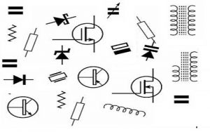
Different Electronic Component Symbols
There are different electronic components are used to make different circuits, projects like resistors, capacitors, diodes, transistors, wires, amplifiers, etc. Here, each component function and its symbol are discussed below.
Power Supply
The power supply mainly includes cell, battery, ac supply, dc supply, fuse, transformer & earth/ground.
Cell: A cell supplies to a circuit.
Battery: The combination of cells is known as a battery and works as a voltage source. It includes two terminals like small & large, where the small one is negative & larger one is positive. It is denoted with ‘B’
DC Supply: A direct current power supply provides the current in one direction always.
AC Supply: An alternating current power supply provides the current in alternating directions.
Fuse: A fuse is a device used to detach the circuit once excess current flows through it. So that circuit or device can be saved from injury.
Transformer: The transformer is used as an AC power supply and it includes two coils namely the primary & secondary. The main function of a transformer is to step up or step down the voltage and it is denoted with ‘T’.
Earth/Ground: Earth or ground is used in different circuits to signify the zero voltage supply.
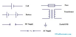
Electronic Circuit Symbols of Power Supply
Wires
A wire signifies a conductor that conducts current and it is also called an electric line/ power line. The wires include wires joined and unjoined wires.
Connected Wires: It signifies the two conductor’s connection
Unconnected Wires: It signifies the two unconnected conductors/ wires.
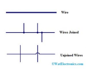
Wires
Resistors
Resistors are electrical and electronic components that are used to restrict the flow of current within the circuit. There different kinds of resistors & their symbols are shown below.
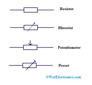
Resistors Symbols
It is a variable resistor including two terminals which are normally used for controlling the flow of current within the circuit. These are used in power control, tuning circuits like ovens, heaters, etc.
Preset
It is a small variable resistor and it is also called a Trim-Pot or Trimmer Resistor. These are mainly used to regulate circuit sensitivity such as light or temperature.
Thermistor
A thermistor is a temperature-sensitive resistor used in different circuits like current limiting, over-current protection, temperature sensing, etc.
Please refer to this link for Electronic Devices and Circuits MCQs
Varistor
A varistor is a voltage-dependent resistor, used to protect the circuit from voltage spikes & extreme transient voltages.
Magneto Resistor
The magneto resistor or MDR (magnetic dependent resistor) is used in position sensors, ferrous material detection, electronic compass, etc.
LDR –Light Dependent Resistor
The LDR is a Photo Resistor, used in light detecting applications.
Tapped Resistor
This is a fixed and wire-wound type resistor including one otherwise more terminals through its length. These are used in the applications of the voltage divider.
Attenuator
The attenuator is used to reduce the signal power & these are designed with simple voltage dividers.
Memristor
The memristor’s resistance can be changed based on the way of charge flow. These can be used in non-volatile memory, logic or computation, signal processing, etc.
Capacitors
The capacitor is an electrical and electronic component, used to store electrical energy. It comprises two metal plates that are divided through a dielectric material. It is used as a filter, so it allows AC signals & blocks DC signals. It is denoted with ‘C’.
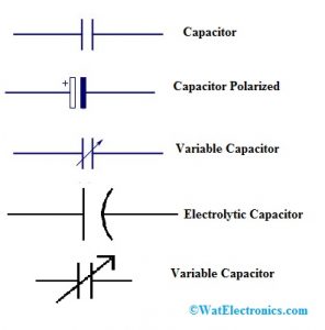
Capacitors Symbols
Polarized Capacitor
These are small capacitors including high capacitance. These are applicable in DC circuits.
Non-Polarized Capacitor
These capacitors store the energy in the electrical form. These types of capacitors are available in big sizes including small capacitance. These are used in AC & DC circuits.
Electrolytic Capacitor
Approximately all types of electrolytic capacitors are polarized & therefore these are used in DC circuits.
Variable Capacitor
The capacitance of this capacitor can be adjusted by rotating the knob and these are used to regulate the frequency for tuning.
Diodes
A diode is a two-terminal component, used to permit the flow of current in one direction only. It is denoted with ‘D’.
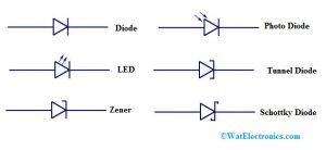
Diodes Symbols
Zener Diode
This kind of diode allows the current flow in reverse direction also. It is denoted with ‘Z’.
Photo Diode
Photodiode works like a photo-detector & the main function of this is to change the light into its equivalent current or voltage.
Tunnel Diode
This kind of diode has high-speed operation because of its usage within quantum mechanical effects.
Schottky Diode
The diode has a large forward voltage drop & thus used in switching circuits.
Transistors
A semiconductor device like a transistor is used to switch or amplify electric power as well as electronic signals. It includes three terminals namely base, emitter, and collector.
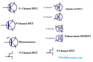
Transistors Symbols
PNP Transistor
In a PNP transistor, the N-type semiconductor is arranged with two P-type semiconductors. Transistor will be activated once the BE (base-emitter) junction is connected in reverse bias. These transistors are used in switching & amplifying applications.
NPN Transistor
In an NPN transistor, the P-type semiconductor is sandwiched in between two N-type semiconductors. It is turned ON once the BE (base-emitter) junction is connected in forwarding bias. These are frequently used in amplifying as well as switching applications.
N- Channel JFET
This transistor is made with n-type Si bars to form two PN- junctions at the surface. In N-channel, the majority of charge carriers are electrons.
P-Channel JFET
This transistor is made with a p-type Si bar & forms two PN-junctions at the surface In P-channel FET, the majority of charge carriers are holes.
Enhancement MOSFET
This kind of MOSFET includes a positive gate operation & negative charges will be induced into the n-channel. So the number of negative charges increases, enhancing the channel conductivity.
Depletion MOSFET
The depletion-mode includes a negative gate operation and it decreases the depletion layer’s width.
Phototransistor
The phototransistor is used to change the energy of light to its equivalent electrical energy when the light drops on it. This transistor can be used in light detecting applications.
Photo Darlington
This kind of Transistor is related to phototransistor through extremely sensitivity & high gain.
Darlington Transistor
This kind of transistor generates a high current gain. These transistors are used in display drivers, o/p stages of audio amplifiers, power regulators, etc.
Logic Gates
In digital systems, logic gates are the basic building blocks. These gates include one or more inputs and one output. The main relationship between the input & the output mainly depends on specific logic. So based on this logic, logic gates are termed with different names.
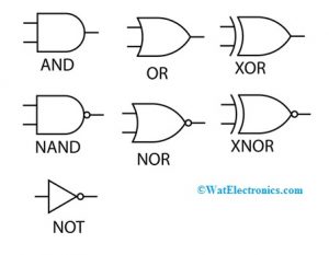
Logic Gates
AND Gate
If both the inputs of the AND gate are high or low then the output will be high.
OR Gate
If any one of the inputs is high then the output will be high.
NAND Gate
NAND gate is the complement of AND gate. When both the inputs are high then the output will be low or high.
NOR Gate
The compliment of OR gate is – NOR gate. If both the inputs are high or low, then the o/p of this gate will be high.
NOT Gate
Not gate inverts the input.
EXOR
In the Exor gate, if both the inputs are not the same then the output will be high
Ex-NOR
The negation of ExORgate is ExNOR. If both the inputs are identical then the output will be high.
Antennas
The antenna changes the electrical power into radio signals & it is used within wireless communication for transmitting/receiving the signals.
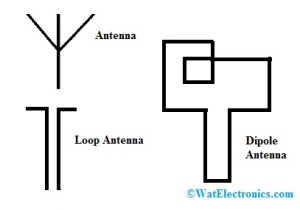
Antennas
Loop Antenna
As the name suggests, this antenna looks like a wire shape otherwise electrical conductor. These are used as receiving antennas within the range of low-frequency.
Dipole Antenna
The dipole antenna is used in shortwave transmission, FM receivers & set-top TV.
Switches
A switch is used to connect or disconnect the conducting lane within the circuit, disrupting the flow of current otherwise redirecting it from conductor to conductor.
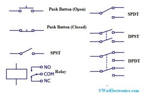
Switches
Push Button (Open)
When the push button is ON then the switch will be ON otherwise it will be OFF.
Push Button (Closed)
This switch is in an ON state and when it is released, this switch will go to OFF condition.
SPST Switch
SPST stands for single pole single throw and this switch works like an ON or OFF switch. Poles will describe different circuits & it can be linked to & throws describes the several positions that a pole unites
SPDT Switch
SPDT stands for Single pole double throw. This kind of switch permits the flow of current in any one of the two ways through changing its place.
DPST Switch
DPST stands for Double pole single throw & this switch can drive multiple circuits at a time.
DPDT Switch
DPDT stands for Double pole double throw. This kind of switch can connect four circuits by altering the location.
Relay Switch
This switch controls the AC Loads through the applied DC voltage to the coil.
Audio & Radio Devices
The audio devices mainly include a microphone, earphone, loudspeaker, piezo transducer, amplifier & aerial.
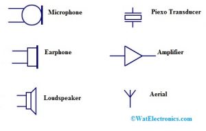
Audio and Radio Symbols
Microphone
The microphone is used to change the sound to its equivalent electrical energy and it is denoted with MIC.
Earphone
The reverse process of a microphone is earphones and it changes the energy from electrical to sound.
Loudspeaker
The operation of a loudspeaker is similar to an earphone; however, it changes the electrical energy into sound.
Piezo-Transducer
This transducer changes the energy into sound.
Amplifier
The amplifier is used to amplify a signal and it is mainly used to signify a complete circuit instead of one component.
Aerial
Aerial is used to send or receive signals and it is denoted with ‘AE’.
Output Devices
The output devices are lamp, indicator lamp, heater, inductor, motor, bell & buzzer.
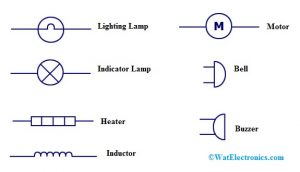
Output Devices
Lighting Lamp
A lighting lamp is mainly used to supply the light for the o/p.
Indicator Lamp
An indicator lamp is used to change the energy from electrical to light. The best example of this is the warning light used on a car dashboard.
Heater
The heater is one kind of transducer that is used to alter the energy from electrical to heat.
Inductor
The inductor is mainly used to generate a magnetic field once a fixed current is supplied throughout a coil of wire. It is used in tank circuits, motor & it is denoted with ‘L’.
Motor
A motor is an electrical device, used to change the energy from electrical to mechanical. It is denoted with ‘M’.
Bell
Bell is used to generate a sound like the output, based on the electrical energy generated like the input.
Buzzer
The buzzer is used to generate the sound as an output equivalent to the electrical energy within the input.
Meters
A meter is one kind of instrument that calculates & records magnetic or electrical quantity like current or voltage. The different kinds of meters are voltmeter, ammeter, galvanometer, ohmmeter & oscilloscope.
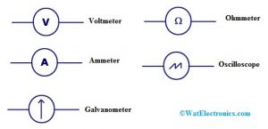
Meters
Voltmeter
A voltmeter is used to calculate the voltage at a fixed point within the circuit.
Ammeter
An ammeter is used to gauge the flow of current at a specific point in the circuit.
Galvanometer
A galvanometer is a device, used to gauge extremely small currents like 1 milliampere otherwise below.
Ohmmeter
An ohmmeter is used to measure the circuit’s resistance.
Oscilloscope
An oscilloscope is mainly used to gauge the voltage & time period of signals.
Amplifiers
An amplifier is used to increases the current, voltage otherwise signals power. These are used in broadcasting & wireless communications & in all types of audio devices.
Circuit Notation & Reference Designators
Once a circuit diagram is designed, then it is essential to recognize the individual components. This is most significant once using a parts list because different components on the schematic diagram can be cross-linked to the list of parts. It is also important to recognize components because they are frequently marked on the PCB so that the components on the circuit can be easily recognized.
To recognize components, a reference designator of the circuit is used. Generally, this designator includes one or two letters through a number.
The letters specify the type of component & the number defines the exact type of component. An example may be C45, R13, etc.
To normalize the way where components are recognized in circuits, the IEEE launched an IEEE 200-1975 standard like the “Standard Reference Designations & it is mainly used for Electronics & Electrical components & devices.
Some of the commonly used schematic reference designators for different components are listed below.
- Attenuator – ATT
- Test point – TP
- Bridge Rectifier – BR
- Transformer – T
- Battery – BT
- Switch – SW
- Capacitor – C
- Switch – S
- Diode – D
- Resistor – R
- Fuse – F
- Transistor – Q
- Integrated Circuit – IC
- Power Supply –P
- Connector jack – J
- Plug – P
- Inductor – L
- Loudspeaker – LS
Please refer to this link to know more about XNOR Gate MCQs, Integrated Circuits MCQs.
Thus, this is all about an overview of electronic circuit symbols and their working. These symbols signify electronic components within the schematic diagram. Although the standards of these symbols vary based on the country, so they are set by ANSI & IEC to signify these components. These circuit symbols are utilized in schematic diagrams to explain the interconnection of a circuit.