The NPN or Negative-Positive-Negative is a general-purpose BJT (bipolar junction transistor). This is a general-purpose semiconductor device that amplifies or switches electronic signals within electronic circuits. This transistor has the highest voltage rating and handles a continuous collector current. These transistors are available in the TO-92 package which makes them integrate easily into a variety of electronic designs. This transistor allows current flow from the collector terminal to the emitter whenever a small amount of current is provided to the base terminal. It reduces power losses throughout conduction within switching applications. These are known for reliable performance, so they work effectively within diverse environments. This article overviews the BC546 NPN transistor, pin configuration, specifications, and applications.
What is BC546 NPN Transistor?
BC546 is an NPN bipolar junction transistor, designed to be used in amplification, switching, H-bridge, current mirror, and impedance circuits. This transistor is from the Si epitaxial planar transistor category. It is a low-power transistor including three layers two N-doped & one P-doped layer. So, the P-doped layer is sandwiched among two N-doped layers.
In addition, this transistor also carries simply two PN junctions wherever one junction is forward biased and remaining junction is reverse biased. BC546 transistor is a current-controlled device where a small amount of current at the base is used mainly to control the large amount of current at the remaining two terminals. This transistor turns ON whenever the BE voltage level exceeds 0.55.
While looking for a suitable transistor for your application based on a few factors, it is very important to look into a few points on How to Select a Transistor.
Working
The BC546 transistor works with the BE voltage to control the flow of current throughout the CE path. Whenever the base terminal is held at GND, then both the collector & emitter terminals are reverse-biased or left open. Whenever a signal is given to the base terminal, then emitter and collector terminals are forward-biased or closed.
In the BC546 transistor, charge carriers are responsible for its conductivity but the majority of charge carriers are electrons. The base terminal of this transistor is positive as compared to the emitter which is used for controlling the number of electrons. Whenever voltage supply is applied at the base then it gets biased & draws current therefore controlling the large current at both the emitter & collector. In this transistor, the flow of current will be from the collector terminal to the emitter.
BC546 is a low-current transistor thus the highest amount of current that could be supplied throughout the Collector pin is 100mA, so we cannot connect any load that consumes >100mA & load voltage >30V. When this transistor is fully biased then it can allow a maximum of 100mA to flow across the collector and emitter. This stage is called the Saturation Region. When the base current is removed the transistor becomes fully off, this stage is called the Cut-off Region.
BC546 Transistor Pin Configuration:
BC546 transistor includes three terminals emitter (E), base (B), and collector (C). However, these three terminals are not the same in doping concentration. These three terminals are used for mainly external connection through various electronic circuits.
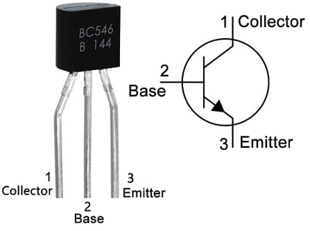
BC546 Transistor Pin Configuration
- Pin-1(Collector): The collector terminal allows the flow of current and is connected normally to load.
- Pin-2 (Base): This terminal controls the transistor biasing by turning ON/OFF.
- Pin-3 (Emitter): This terminal is connected normally to GND where current drains out throughout this terminal.
Features & Specifications:
The features and specifications of the BC546 NPN transistor include the following.
- It is a three-terminal NPN transistor.
- It is available within the To-92 Package.
- Its current gain or hFE ranges from 110 to 800.
- The continuous collector current or IC is 100mAmps.
- Collector to emitter voltage or VCEO is 65 Volts.
- Collector to base voltage or VCB0 is 80Volts.
- The emitter to base voltage or VBE0 is 6 volts.
- Its transition frequency is 150MHz.
- Its gain value is 800 which determines the amplification capacity of the transistor.
- This transistor’s junction temperature is 150 °Centigrade.
- Its operational temperature ranges from –65 to +150 °Centigrade.
Equivalent & Complementary Transistors
Equivalent BC546 NPN transistors are; 2SC4145, 2SD1701, 2SD1698, 2SD1981, 2SD2213, 2SD1978, HIT667, KTC1026, 2SD2296A and KTC3200. Complementary BC546 NPN transistors are; BC559 and BC556.
Replacing a suitable transistor in any circuit based on requirement is very important. To know how to replace it, please refer to this; Replacing Transistors in Electronic Circuits: Factors and Considerations.
BC546 Transistor Modes
The modes of the BC546 transistor are active mode, cut-off mode, saturation mode, and reverse active mode which are discussed below.
- In active modeBC546 NPN Transistor, the transistor base terminal is responsible for its action, so the applied voltage that draws a small amount of current is used to control a large amount of current at both the emitter & collector terminals.
- The transistor in cut-off mode works like an open switch, thus there is no flow of current between the two terminals.
- Saturation mode works like an ON switch wherever current supplies from the collector terminal to the emitter. So the voltage variation between the collector & emitter in this condition is zero.
- The transistor in reverse active mode works like an active mode however the current direction will be reversed but supplies from the emitter terminal to the collector.
Variable Current Limiter Circuit
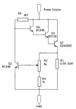
The variable current limiter circuit is shown below. This circuit provides automatic current limiting up to 8.4Amps. This current limiting circuit doesn’t drop the voltage but keeps the voltage drop at the lowest until a certain amount of current is exceeded. So this current limit is changeable from 1.4 Amps to 8.4 Amps with a potentiometer. To provide a different current limiting range, the component value can be modified.
The required components to make this adjustable current limiter circuit mainly include; a power source, transistors like; Q2N3055, BC546, and BD139, and resistors 5K, 1K, 4K7, and 0.5R. Connect the circuit as per the diagram shown below.
Variable Current Limiter Circuit
Working
The R1 resistor in the above circuit is used to sense the current. If the current drawn through the load reaches 1.2Amps at potentiometer R2 at least resistance then the voltage across the R1 resistor reaches 0.6V & Q2 starts conducting, therefore shorting the voltage at Q4 base to ground. So, this decreases the base current & also sensed output voltage by the load to avoid the flow of current further. If you require the current limiter to restrict at a lower threshold range, then you can modify the R1 to 1R to get 0.7Amps to 4.2Amps adjustment range.
2N3055 transistor in the circuit has power dissipation ability in the bad case that the load is shorted to GND. If you restrict the current supply to 8.4 Amps then this circuit handles a maximum 14V source voltage. Similarly, when you limit the current supply at 4.2Amps then it handles up to 27Volts source voltage.
So the maximum voltage supply this circuit can handle is 60 volts, however, at that highest voltage, you can set the current limit safely at 1.9A within the extreme state whenever the load is shorted to GND. Please check the Q1 transistor has an adequate heat sink.
Connecting a base resistor to the base terminal of the transistor is mandatory to avoid it being damaged. So, Please refer to this link for; Choosing Base Resistance for Transistors in Electronic Circuits.
1000Watts Amplifier Circuit Diagram
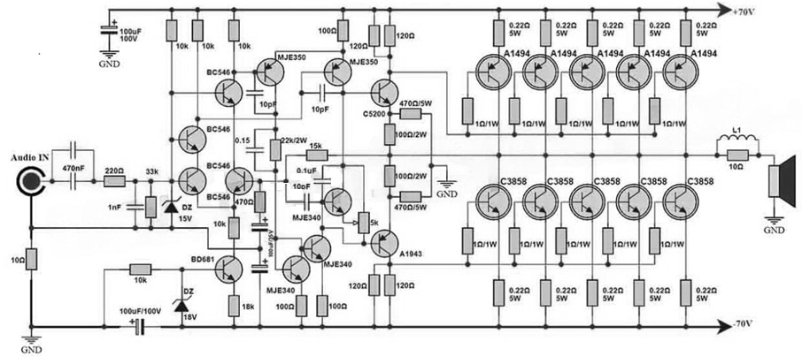
This is a very efficient and powerful audio amplifier circuit used in various applications. This circuit can be built with different transistors which use the most advanced technology for delivering an impressive output power.
The required components to make this circuit mainly include; ±70V DC power supply, 2SC3858 transistors, 2SC5200, 2SA1494, 2SA1943,MJE350, MJE340, BC546, BD681, 15V and 18V Zener Diodes. Connect the circuit as per the diagram shown below.
1000Watts Amplifier Circuit Diagram with BC546 Transistor
Working
This circuit works by using 2SA1943, 2SC5200, MJE350, BC546, and MJE340 transistors within the driver & preamplifier sections whereas SC3858 & 2SA1494 transistors are used in the output section.
This 1000Watt amplifier circuit is designed mainly to provide higher-quality audio amplification with 1000W power output. The output section is the main portion of the circuit because it uses five pairs of 2SA1494 and 2SC3858 transistors which are well known for their exceptional thermal stability and high power handling capabilities which makes them perfect for higher-power audio amplification.
So, the driver & preamplifier sections in this circuit use a combination of transistors like; 2SA1943, 2SC5200, MJE350, BD681, BC546 & MJE340. So these transistors play a fundamental role in audio signal amplification and drive the output transistors very efficiently. Here, the selection of these transistors depends on their suitability for excellent linearity, low distortion characteristics, and high-power applications.
Thus, a 1000W amplifier circuit uses a combination of high-power o/p, driver & preamplifier transistors. This simple circuit design ensures very efficient amplification & high-quality audio output. This circuit can also meet the demanding necessities of high-power audio amplification applications by using transistors with low distortion, outstanding power handling capabilities, & high linearity.
Advantages & Disadvantages
The advantages of the BC546 NPN transistor include the following.
- It has up to 800 decent gain value.
- It is a high-frequency-based NPN transistor used within low-noise amplifier designs.
- It is less weight and very small size which reduces equipment size.
- It operates at low operating voltages which is well-matched with only a few cell batteries.
- It has improved efficiency & compatible with negative ground systems.
- This transistor amplifies the weak signal at the base and generates very strong amplified signals at the collector terminal.
The disadvantages of the BC546 NPN transistor include the following.
- These transistors can generate heat during operation & in high-power range applications, additional intensity scattering systems might be necessary.
- These are delicate to temperature ranges, which affects their exhibition.
- It has less breakdown voltage.
- This transistor has low power handling ability.
- This transistor’s performance in high-temperature environments is poor.
BC546 NPN Transistor Applications
The applications of BC546 transistors include the following.
- BC546 transistor is utilized in linear amplifiers, H-Bridge circuits, current mirrors circuits & impedance circuits.
- This transistor can also be used in astable vibrators, bistable multivibrators, comparator circuits, and oscillator circuits.
- It is used in low-noise and high-voltage amplifier designs.
- It is used in Darlington pair, small loads switching, small signal amplifiers, audio noise filters, Pre-amplifier circuits, etc.
- This transistor is used in low-noise and high-voltage amplifier designs.
- It can be utilized to switch small loads as well as in switching devices.
- It is used in other applications like; audio noise filters, DIY kits & Darlington pairs.
- These are used for industrial control, mobile phones, FFs, TV & high-frequency applications like radio frequency audio circuits.
Please refer to this link for the BC546 NPN transistor datasheet.
This is an overview of the BC546 NPN transistor, pinout, features, specifications, circuit, working, advantages, disadvantages, and applications. It is a low-current transistor where its maximum current ability can be pumped throughout the collector terminal to 100mAmps. So we cannot connect different devices that draw >100mAmps (or) the load voltage is >30V throughout this transistor. It is a good gain of hfe that can reach 800. Here is a question for you, what is a BC547 transistor?