A DC-to-DC converter or DC/DC converter is an integrated circuit that changes one level of DC voltage to another level. These are also known as switching or linear regulators based on the method utilized to adjust the voltage. So these ICs are commonly used in portable devices & also battery-powered devices because different sub-circuits within a device frequently need different voltages. There are different types of DC-to-DC converters; step-up, step-down, boost buck, inverting, or negative voltage. These ICs are necessary for automotive applications, wherever they perform as an intermediary between systems with various voltage levels. So this article explains a DC-to-DC converter like XL6019 IC, its pinout, specifications, and its applications.
What is XL6019 IC?
XL6009 is a non-isolated step-up boost voltage converter IC with high efficiency and adjustable output voltage. This IC changes the input voltage from 5 to 32V DC to 4V to 38V DC output voltage. This regulator IC has a wide input range, DC/DC converter, and current mode which generate either negative or positive output voltages. This IC can be arranged as either a flyback, boost, inverting, or SEPIC converter. Thus, XL6019 IC has an in-built fixed frequency oscillator, N-channel power MOSFET, and current-mode architecture which results in constant operation over a broad range of voltage supply & output voltages.
Working
The XL6019 DC/DC converter IC works by simply storing energy within the magnetic field of an inductor and transferring it to the inductor or a capacitor. So this IC stores energy in the inductor’s magnetic field. So, the capacitor’s voltage enhances beyond the source voltage that supplies energy to the inductor.
XL6019 IC is a current mode regulator with a wide input range that produces positive voltage or negative o/p voltages. This IC can be configured as a flyback, boost, inverting, or SEPIC converter and is designed to be used in portable electronic equipment.
XL6019 IC Pin Configuration:
The pin configuration of XL6019 IC is shown below. This IC includes 5-pins which are discussed below.
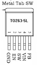
XL6019 IC Pin Configuration
- Pin-1 (GND): This is the ground pin of the regulator IC.
- Pin-2 (EN): This is the enabled pin that controls the IC. Whenever this EN-pin is not in use then it is connected directly to the input power supply to automatically start.
- Pin-3 (SW): This is a power switch o/p pin where the output rectifier and power inductor are connected to this SW pin.
- Pin-4 (VIN): This is the input power pin of the chip which must be bypassed locally.
- Pin-5 (FB): This is the feedback input pin where the feedback voltage is around 0.6V.
Features & Specifications:
The features and specifications of XL6019 IC include the following.
- XL6019 IC is a 5-pin voltage regulator IC.
- This IC is available in the TO263-5L package.
- Its input voltage range is wide from 5V to 40V.
- Its output voltage is positive (or) negative.
- It can be programmed with a single feedback pin.
- The current mode control of this pin provides an outstanding transient response.
- Its switching frequency is fixed like 180 KHz.
- Its maximum switching current is 5A.
- SW pin is built above voltage protection.
- It has outstanding load and line regulation.
- It has internal optimized power MOSFET.
- Its efficiency is high up to 94%.
- It is built with a soft start function, frequency compensation, thermal shutdown, current limit, etc.
- Maximum output ripple is 100mv.
- Its load regulation is ± 0.5%.
- Industrial working temperature ranges from -40 ° C to + 85 ° C.
Equivalents & Alternatives:
Equivalent XL6019 ICs are; LM2577S, LM2596S and AMS1117-3.3V. Alternative XL6019 ICs are; XL6009 IC, XL4015, XL6005, XL7015, etc.
DC to DC Adjustable Step-up Converter Circuit with XL6019 IC
The DC to DC adjustable step-up converter circuit using XL6019 IC is shown below. So the required components to make this circuit mainly include; XL6019E1 IC, M7 SMD Diode, 35V 220uF SMD aluminum electrolytic capacitor, 1uF ceramic capacitor, 33uH (330) Inductor, Resistor, SS34 Schottky power diode, 100uF 50Volts SMD aluminum electrolytic capacitor, 10kΩ variable resistor, resistors like 330Ω, 1kΩ & SMD LED.
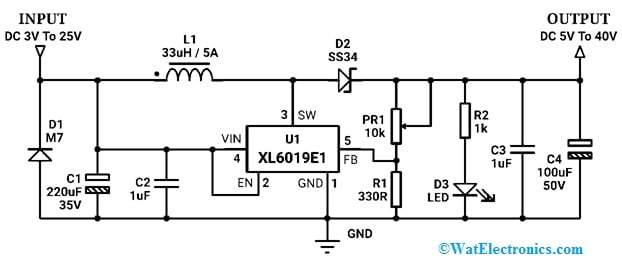
DC to DC Adjustable Step-up Converter Circuit with XL6019 IC
Working
The DC to DC step-up converter circuit working is very simple. Thus, the XL6019 IC includes a soft start, error amplifier, 1.25V integrated reference, OVP, OVLO, PWM comparator, 80mΩ integrated power MOSFET with driver, RS latch, thermal sense, and OCP.
When the input DC supply is provided to the circuit, the C1 capacitor will get charged through the series inductor and Schottky diode setup. This diode is located in reverse bias to avoid reverse polarity i/p voltage.
At first, the pin-4 or Vin of the IC gets the input DC voltage supply, it starts ~220 kHz switching throughout its pin-3 (SW) and a maximum 5A current is supplied directly throughout the L1 inductor from the DC input source. Here, the SW pin is the drain of the inside MOSFET switch & swing between ground & 3-25V.
The pin-2 (EN) of the IC is the ON/OFF control input, which is generally connected to the i/p supply for automatic startup. In the turn-on stage of the chip, it induces a magnetic field within the inductor and generates a high-voltage spike. So the voltage spike in the turn-off stage of IC passes throughout the D2 diode which blocks and reverses current toward the circuit & raises the voltage of the C3 capacitor to 40V. Here, ceramic capacitors are directly used in the I/O of the converter to eliminate the noise within voltage.
The output voltage can be simply controlled with a PR1 multi-turn variable resistor & R1 fixed resistor voltage divider arrangement, which refers to a 1.25Volts signal to the FW pin of IC. Thus, the inside control logic adjusts easily to the necessary output voltage level and maintains the set voltage within a load condition continuously.
Advantages & Disadvantages
The advantages of XL6019 IC include the following.
- The XL6019 achieves up to 97% conversion efficiency.
- Its input voltage range is wide.
- This IC generates either positive (or) negative o/p voltages.
- It is well known for its stable operation and precise voltage control over a wide range of voltage supply & output voltages.
- This IC is in-built protected with thermal protection, current limit function & over-current protection.
- Its fixed frequency oscillator and current-mode architecture allow for constant operation over a wide voltage range.
- It has outstanding line & load regulations.
- This IC has an in-built soft-start function, TTL shutdown ability, and built-in frequency compensation.
The disadvantages of XL6019 IC include the following.
- It is a step-down voltage regulator, so step-down operations are only possible.
- The loss is huge and poor efficiency whenever there is a huge variation in between the I/O voltage.
- A large quantity of heat is produced whenever the variation between the I/O voltages is large, thus measures to dissolve the heat are necessary.
Applications
The applications of XL6019 IC include the following.
- The XL6019 IC is mainly designed for convenient electronic equipment to produce either positive (or) negative o/p voltages.
- This IC can be configured as a fly-back, boost, inverting converter, or SEPIC.
- This can be used as an adjustable boost power supply module including features like built-in thermal protection, over-current protection & reverse connect protection.
- This is a DC-to-DC converter IC that can be used in different applications like; portable electronic equipment, notebook car adapters, automotive, industrial buck-boost, boost & inverting converters, battery-powered devices, etc.
- It can be used in robotics, solar power systems, automation projects, etc.
- This can be used for general voltage-boosting applications.
Please refer to this link for the LM2596S IC Datasheet.
Thus, this is an overview of the XL6019 high-power boost converter IC which delivers up to 5Amps of o/p current. This IC works over a wide range of input voltage and has a 180 kHz fixed switching frequency. This IC includes soft-start, internal compensation & protection features such as over-current protection and thermal shutdown. It is ideal where reliable step-up voltage is necessary due to its robust design and high efficiency. Here is a question for you, what is LM2596S IC?