A transistor is a basic building block and semiconductor device in modern electronics. It is designed with semiconductor material with a minimum of three terminals, used for connection to a circuit. So, the main function of a transistor in circuits is to either switch or amplify electrical signals or power. It includes two PN junction diodes connected one after the other. The fundamental idea behind a transistor is that it allows you to control the current flow throughout one channel by changing the intensity of a smaller current supplied throughout a second channel. Thus, this article discusses an overview of the MPS651 transistor, pinout, specifications, circuit, working, and applications.
What is MPS651 Transistor?
The MPS651 is an NPN type three terminal bipolar junction transistor, available in a TO-92 package. It is a plastic encapsulated transistor mainly designed to be used in general-purpose linear as well as switching applications which requires up to 100 mA collector current.
While looking for a suitable transistor for your application based on a few factors, it is very important to look into a few points on How to Select a Transistor.
Working
MPS651 transistor works and uses base-emitter voltage to control the flow of current throughout the collector-emitter lane. So this transistor operation is based on the electrons movement because these are the majority charge carriers.
Whenever a small current is provided to the base-emitter junction in forward bias then electrons move to the base terminal and generate the emitter current. Thus, whenever the collector region is reverse-biased, then it attracts the charge carriers at the collector. These transistors amplify weak signals at the base end and generate strong amplified signals at the collector end.
Pin Configuration:
The pin configuration of the MPS651 Transistor is shown below. This transistor includes three terminals which are discussed below. So, the flat side of the transistor has leads that are pointed down, thus the three terminals emerging from the transistor are, from left side to right; the emitter, base & collector terminals.
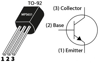
MPS651 Transistor Pin Configuration
- Pin-1(Emitter): The Emitter terminal emits the charge carriers.
- Pin-2 (Base): The base terminal biases the transistor which transmits all the charge carriers from the emitter terminal to the collector with minimum loss.
- Pin-3 (Collector): The collector terminal gathers all the charge carriers from the emitter.
Features & Specifications
The features and specifications of the MPS651 Transistor include the following.
- It is an NPN transistor.
- It is available in the TO-92-3 package.
- The mounting type is through the hole.
- Its collector-to-emitter voltage maximum is 60 Volts.
- Its maximum collector to base voltage is 80 Volts.
- Its emitter-base voltage maximum is 5 Volts.
- The maximum continuous collector current is 2 Amps.
- Collector dissipation is 0.625 Watts.
- DC Current Gain or hfe is 75.
- The minimum transition frequency is 75 MHz.
- Collector current maximum or Ic is 800 mAmps.
- The maximum collector-to-emitter breakdown voltage is 60 Volts.
- Maximum Vce saturation @ Ib, Ic is 500mV at 2A, 200mA.
- Its collector cutoff current or ICBO maximum is 100nA.
- DC gain or hFE minimum is @ Ic, Vce is 75 at 1A, 2Volts.
- Maximum power is 625 mW.
- The transition frequency or Tf is 75MHz.
- Its operating & storage junction temperature ranges from -65 to +150 °C.
Equivalent & Other Transistors
The equivalent and replacement MPS651 transistor is MPS651G. The complementary MPS651 transistor is the MPS751 PNP transistor. The SMD versions of this transistor which have related parameters and are designed mainly for surface mounting are BSP51 in SOT-223, FMMT491Q (SOT-23), FMMT491 in SOT-23, KTC4378GR in SOT-89, KTC4378 in SOT-89 and KTC4378Y in SOT-89. So, the Lead-free version of this transistor is the MPS651G transistor.
Replacing a suitable transistor in any circuit based on requirement is very important. To know how to replace it, please refer to this; Replacing Transistors in Electronic Circuits: Factors and Considerations.
How to use an MPS651 Transistor in a Circuit for a Long Time Securely?
To use this MPS651 transistor very securely and to get lasting performance within a circuit, it is recommended to not use it at its maximum ratings. Thus, always stay < 20% of its total maximum ratings. Do not drive any load above its maximum collector current and its maximum CE voltage. So, this transistor must be used at above -65 to +150 °C temperature.
Touch Control-based 9V High Efficiency LED Flashlight.
The touch control-based 9Volts high-efficiency LED flashlight circuit is shown below. So the required components to make this simple circuit mainly include; two blue or white 25mA LEDs, 1N5819 silicon diode, BC327-25 (or) MPS751 PNP transistor, MPS651 NPN Transistor, 220uH coil inductor, 10uF 10volt capacitor, 1000pF capacitor, 10k & 1M resistors and 9V battery. Thus, connect this circuit as per the diagram shown below.
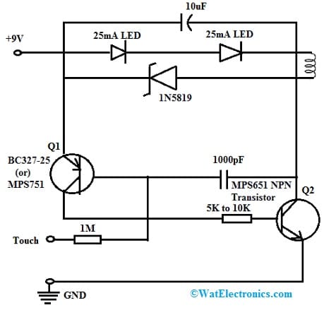
Touch Control-based 9V High Efficiency LED Flashlight
Working
This circuit efficiency comes from the inductor coil and the tiny 1000pF capacitor. The circuit starts working whenever moisture from the finger turns the Q1 transistor ON, which switches Q2 thus, the current flow from the battery is drawn throughout the two LEDs, the coil, through Q2 & to GND. Here the 1000pF capacitor forces both the transistors to saturate & improve efficiency. So when the two LEDs need only 6.5v to light up, the inductor coil builds up its charge by the excess of 2.5 volts.
In the above circuit, a 1000pF capacitor cuts off the transistors whenever the coil saturates & its magnetic field fails. So the supply voltage that supplies throughout the diode keeps the LEDs ON. Thus, the oscilloscope trace displays how this cycle replicates again and again, approximately ¼ million times a second.
Thus, power is drawn only from the battery about half of the time, whereas the coil ‘recycles’ the surplus power the other times. As a result, the LEDs maintain complete brightness without exhausting the battery continuously.
This is a very simple example switch-mode circuit. Not like series regulators such as the LM317 & 7805 which burns up additional power like heat, this circuit stores the extreme energy within a coil to maximize battery life.
Connecting a base resistor to the base terminal of the transistor is mandatory to avoid it being damaged. So, Please refer to this link for; Choosing Base Resistance for Transistors in Electronic Circuits.
MPS651 Transistor Applications
The application areas of this MPS651 transistor include the following.
- MPS651 transistor is used in relays, voltage regulators, industrial and ramp drivers, etc.
- This transistor is used as a general-purpose switch & amplifier that requires high gain at a higher collector current.
- It is used in small signal amplifier circuits like; preamplifiers, RF amplifiers & audio amplifiers.
- This transistor can be used in general-purpose amplifiers & switching applications to control different loads like LEDs, relays, etc.
- It is used within transistor die protection devices.
- This transistor can be used in oscillator circuits that produce periodic signals like; sine waves, square waves (or) other waveforms.
- It can be used in different signal-processing circuits like; filters & mixers.
- It can function as a main part of logic gates, FFs & other digital logic circuit elements within digital electronics.
- It is used in circuits that are designed for current limiting and regulation to defend different components against over-current conditions.
Please refer to this link for the MPS651 Transistor Datasheet.
Thus, this is an overview of the MPS651 transistor, pinout, features, specifications, circuit, working, and applications. So, these are very small, use low power, are more rugged, and have longer life spans. So these are inexpensive to manufacture which makes them a popular choice to utilize in low-cost consumer electronics. Here is a question for you, what is BSP51 transistor?