The 2N3906 is a PNP BJT produced primarily by Onsemi Semiconductor Company. It is commonly used in low-power switching or amplifying applications. This transistor is designed mainly for low electric current, power & medium voltage, but it can work at quite high speeds. This is one of the most famous discrete-type transistors that hobbyists, circuit designers & makers utilize within their electronics projects. Therefore, this transistor is available in a TO-92 DIP plastic body package. Apart from that, it is also available in a couple of SMD packages like; SOT-23 & SOT-223. This article discusses an overview of the 2N3906 transistor, pin configuration, specifications, and its applications.
What is a 2N3906 Transistor?
A special-purpose PNP transistor that has been used generally for low power switching, low current medium voltage & amplification is the 2N3906 transistor. This transistor is mainly fit for high-speed switching. It is available in the marketplace in different families with different features and characteristics like; 2N3609RL1, 2N3906RLRGA & 2N3903G which make it change from each other.
Its collector current ranges from 10μA to 100mA, so, it could be utilized for low current gain to higher current gain. The collector current of the 2N3906 transistor is 200 mA, collector emitter, and collector-to-base voltages are 40 V with 300 mW of power dissipation. Its transition frequency is 250 MHz, with a beta of a minimum of 100. In addition, the most common package of this transistor is the TO-92 package including both straight leans & bent leads.
While searching for an appropriate transistor for your requirement based on different factors, it is very significant to follow these few steps on How to Select a Transistor.
Working
The working of the 2N3906 transistor is whenever the base pin of the transistor is held at GND, the emitter and collector terminals will be forward biased or closed. Similarly, when the signal is given to the base pin, it will be reverse-biased or opened.
This transistor works as an amplifier in the active region, because its emitter-base (EB) junction is forward-biased & the collector-base (CB) junction will be reversed-biased. Once this PNP transistor is completely biased then it allows 200mA of maximum current to supply across the CE junction known as saturation region. The typical voltage permitted across the collector to emitter or base to emitter ranges from 40 to 5V correspondingly. Once the voltage supply at the base terminal is removed the transistor will be turned off which is known as Cut-off Region. The voltage from base to emitter could be approximately 5V.
For transistor biasing, we have to provide 5mA of current supply to the base pin. The gain value of this transistor ranges from 110 to 300, which decides the amplification capacity. Thus, the highest amount of current supply that could be supplied throughout the Collector terminal of this transistor is 200mAmps. Therefore, we cannot connect any loads that use >200mA with this transistor.
Pin Configuration:
The pin configuration of the 2N3906 transistor is shown below. So this transistor includes three pins which are utilized for various configurations. 2N3906 is a PNP transistor thus current supply from the emitter terminal to the collector.
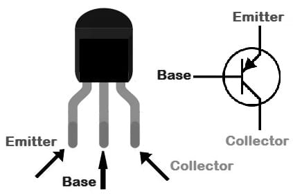
2N3906 Transistor Pin Configuration
- Pin-1 (Emitter): This pin drains out the current supply throughout this terminal.
- Pin-2 (Base): This pin controls transistor biasing.
- Pin-3 (Collector): This pin allows the flow of current.
Features & Specifications:
The features and specifications of the 2N3906 transistor include the following.
- It is a PNP Bi-Polar transistor.
- This transistor is available in the To-92 Package
- Its maximum DC gain or hFE is 300.
- The emitter to base voltage or VBE is 5V.
- The maximum base current or IB is 5mA.
- Its collector capacitance is 5pF.
- The maximum collector current is 200mA.
- Its collector-to-emitter saturation voltage is 0.25V.
- Its continuous collector current or IC is 200mAmps.
- Collector to emitter voltage or VCE is 40Volts.
- Collector to base voltage or VCB is 40Volts.
- Its Junction operating temperature ranges from -55 to 150 degrees centigrade.
- Its forward current transfer ratio minimum is 100.
- The transition frequency is 250MHz.
- The power dissipation minimum is 250mW.
- DC gain is 60.
Equivalent & Alternative Transistors
Equivalent 2N3906 transistors are; 2N4403, MPSA92, MPSA13, ZTX555 & MPSA55. In additio, its alternative 2N3906 transistors are; BC558, BC157, 2SA1943, S8550, BD140, TIP42, TIP127, many more.
An appropriate transistor replacement within any application circuit depending on requirement is very significant. To identify how to change it, need to refer to this link for knowing; Replacing Transistors in Electronic Circuits: Factors and Considerations.
DC Voltage Booster Circuit with Transistors
A simple DC voltage booster circuit design using a transistor circuit is shown below. This circuit boosts a low-level 1.5V DC signal to a significantly higher 3V DC level. This circuit is used commonly in different applications where a higher DC power input is required about 60Volts to 80Volts DC. Generally, DC-to-DC converters or boosters are simple electronic circuits that help in increasing or decreasing the DC voltage to obtain the preferred voltage level.
The required components to make this DC voltage booster circuit using transistors mainly include; a Breadboard, 1.5V battery, Zener diode, Transistors like; 2N3906 & 2N3904, Resistors like; 100KΩ, 200KΩ & 1KΩ, 200μH – 470μH Inductor and 1N4148 diode. Connect this circuit as per the circuit shown below.
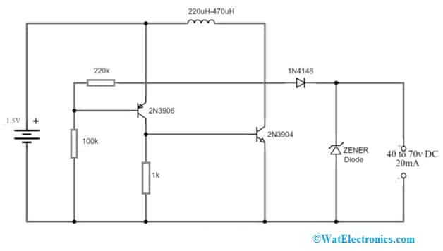
DC Voltage Booster Circuit with Transistors
Working
This simple voltage booster circuit helps in boosting the 1.5V to 40Volts to 70V DC. This circuit’s output current is approximately 20mAmps. This circuit is used where a high voltage and low input current is required. Here, the output mainly depends on the utilized inductive coil.
For instance, the maximum output for a circuit with a 220μH coil will be approximately 40V DC. Likewise, a 470μH coil circuit can give up to 70V DC. Here the desired voltage level is attained by simply connecting a Zener diode to the output terminals parallelly. So, if you need 18Volts DC then you can utilize an 18Volts Zener diode.
In the industrial sector, conversion of a fixed voltage DC source into a variable voltage DC source is required. So, a DC converter is considered to be a DC equivalent to an AC transformer through a continuously changeable turn ratio. Similar to a transformer, this converter can step up or step down a DC voltage source. These converters can also work as switching mode regulators for converting a DC voltage usually unregulated to a regulated DC o/p voltage.
This DC voltage booster circuit is used in small machines and domestic appliances. This circuit is used mainly for processes like; pulse creation for academic and research purposes.
A base resistor connection to the transistor’s base terminal is compulsory to keep away from damage. So, please refer to this link for; Choosing Base Resistance for Transistors in Electronic Circuits.
2N3906 Transistor Applications
The applications of the 2N3906 transistor include the following.
- 2N3906 transistor switches between higher voltage and lower current loads in TV and home appliance equipment.
- Loads with peak voltages equal to 40V are best handled.
- This transistor is used in different switching applications.
- In these circuits (inverter, flasher, and converter), it is used.
- This transistor is used to design sirens and dual-LED (or) lamp flashers.
- It is utilized within Darlington Pair.
- Higher-speed switching applications use it.
- In general-purpose audio amplifiers, it is used as a switch for higher voltage, higher gain, lower current, and low saturation voltage applications.
Please refer to this link for the 2N3906 transistor Datasheet.
Thus, this is an overview of the 2N3906 transistor, pinout, specifications, circuit, working, and its applications. This is the most frequently used PNP-type transistor and is very similar to the BC557 transistor apart from its higher collector-to-emitter voltage & thus higher voltage loads can be easily toggled. The gain of this transistor is 300 only, so it is not appropriate for amplifier circuits. If you are looking for a PNP transistor that switches high voltage loads in 0.2Amps then this transistor might be the correct option for you. Here is a question for you, what is a BC557 transistor?