The TDA2822M is a dual audio power amplifier IC developed by STMicroelectronics. This IC uses IC technology composed of various components like transistors, resistors, capacitors, etc. As the name suggests, this IC includes two independent amplifier channels that work as a stereo amplifier to power two separate speakers. This dual nature gives flexibility by allowing for stereo applications or a more powerful mono output within bridge mode, wherever both channels are merged to drive a single larger speaker. In addition, a protection mechanism is incorporated within the chip to avoid problems like load imbalance or overheating by ensuring the reliability & stability of the audio output. This article provides an overview of the TDA2822M IC, pin-out, features, specifications, and applications.
What is the TDA2822M IC?
The TDA2822 is a dual low-voltage power amplifier IC, available in an 8-pin mini DIP package. This IC includes two independent amplifier channels within a single package. This amplifier IC operates with a wide voltage supply range, widely used in audio amplifier applications. This low-voltage power amplifier IC functions to amplify weak audio signals or electrical signals at low voltage supply levels. So these amplifier ICs are commonly used where power conservation and energy efficiency are essential, like battery-powered and portable devices.
The TDA2822 IC is available in a compact size with exceptional audio performance, low distortion, easy-to-implement, wide voltage range, etc. In addition, this IC has become a favorite among electronics hobbyists, audio designers & enthusiasts.
The TDA2822M and TDA2822 IC packages are similar, but there are some variations between them regarding output power and operating voltage. This TDA2822M IC operates from 1.8V to 15V voltage range, whereas the highest operating voltage of the TDA2822 IC is 8V only. So TDA2822M IC exhibits quite high output power within dual-channel mode because it correlates with a rise in voltage, which leads to high output power.
HowTDA2822M IC Work?
The TDA2822M IC works as a low-power stereo audio amplifier that uses a small audio input signal and amplifies it to a strong enough level to drive a connected load. It uses internal circuitry to attain this amplification with the least distortion & low power consumption. Whenever an audio signal is provided to the input pins, the internal circuitry in the IC amplifies the signal by allowing it to drive a load with a significantly higher power output.
The TDA2822M IC operates typically with a wide voltage supply range that ranges from 1.8V to 15V. This IC simultaneously amplifies two separate audio channels by allowing stereo sound reproduction. So the internal TDA2822M IC design is optimized to reduce audio distortion by generating a cleaner sound output. Thus, this IC is used frequently in applications like small speakers, compact audio devices, and portable radios due to its compact size and low voltage requirements.
TDA2822M IC Pin Configuration:
TDA2822M IC pin configuration is shown below. Thus, this IC includes 8 pins, which are explained below.
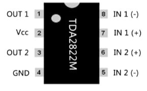
TDA2822M IC Pin Configuration
- Pin-1 (Output1): This is an output1 pin of channel-1 of the IC, used to drive a connected load to the +ve terminal of the audio o/p for the primary channel.
- Pin-2 (Vcc): This is the +ve supply pin of the IC, connected to the +ve terminal of the power supply voltage. This pin provides the required power to the IC.
- Pin-3 (Output 2): This is the output of channel-2, which is used to drive a load connected to the +ve terminal of the audio o/p for the next channel.
- Pin-4 (GND): This is the ground pin for two amplifiers in the IC. Thus, it is connected to the GND reference of the circuit to provide a common reference point.
- Pin-5 (Input 2 (-)): This is the inverting input pin for Channel-2 of the chip. It is the input terminal for the next audio channel, used for the audio signal input.
- Pin-6 (Input 2 (+)): This is the non-inverting input pin for Channel-2 of the chip. Thus, it is the balancing input terminal to Pin-5 that forms the input differential amplifier mainly for the next audio channel. The input signal is in the voltage form at this pin.
- Pin-7 (Input 1 (+)): This is the non-inverting input pin of Channel-1 of the chip, so used for the audio input signal. So the input signal at this pin will be in voltage form.
- Pin-8 (Input 1(-)): This is the inverting input pin of Channel-1 of the IC. It is the opposite input terminal to Pin-7, which forms the input differential amplifier together with the primary audio channel. So the input signal will be in a voltage form at this pin.
Features & Specifications:
The features & specifications of TDA2822M IC include the following.
- TDA2822M is a dual low-voltage power amplifier IC.
- This IC is available in 8-pin DIP (Dual Inline Package) or SMD (surface-mount) packages.
- Its voltage supply ranges from 1.8V to 15V.
- This IC has two channels.
- The mounting style is through the hole.
- Quiescent current or Iq around 6mA, typically at 6V Vcc for each channel.
- The output power is 0.6 watts for each channel at Vcc = 6V and a 4-ohm load.
- Its output configuration is stereo.
- BTL (Bridge-Tied Load) mode is supported for increased o/p power.
- Its THD or Total Harmonic Distortion is 0.2% at f = 1 kHz and Po = 0.5W.
- Channel separation is typically around 50dB at f = 1 kHz.
- It has thermal & short-circuit protection.
- The input bias current is 100 nA.
- It is a Class AB amplifier.
- The gain is 39dB.
- Power dissipation is 1 Watt.
- Its operating temperature ranges from -40 °C to 85 °C.
- The power supply rejection ratio is 40 dB.
Equivalents & Alternatives
Equivalents to TDA2822M ICs are; KA2209, KA2209B, NJM2073, LM380, KA2206B, LM4871, TA8210AH, AN7158, NJM2073, S1A2209A01, etc. So alternative power amplifier ICs are; KA2206B, NJM2073, LM4871, TA8210AH, NTE7155, KA2209, YD2822A, D2822/D2822A, NJM2073D, etc.
Stereo Amplifier Circuit with TDA2822 IC
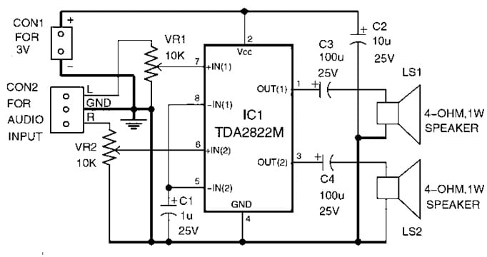
Here a simple stereo amplifier circuit is designed with the TDA2822M IC to amplify the audio signal using mobile devices. This IC is available in an 8-pin DIP package, which is readily available in the market.
So the required components to make this circuit mainly include; TDA2822M IC, VR1 and VR2 10 Kilo Ohm potentiometers, electrolytic capacitors like 1uF 25V, 10uF 25V and 100uF 25V, miscellaneous CON1 (2-pin terminal connector, 3-pin connector, LS1, LS2 4ohm, 1W speaker, 3V battery), etc. Thus, connect this circuit as per the simple circuit shown below.
Stereo Amplifier Circuit with TDA2822 IC
Working
The stereo audio amplifier circuit uses TDA2822M IC, capacitors like C1 & C4, VR1 & VR2, two potentiometers, and two speakers. This circuit’s operating voltage is from 3V DC to 6V DC, but this circuit works with 3V DC (two 1.5V AA batteries). In the above circuit diagram, the LS1 left speaker is connected to pin-1 of IC1 through a C3 electrolytic capacitor. Thus, the LS2 right speaker is connected to pin 3 through the C4 electrolytic capacitor.
Here, pins 5, and 8 are connected and connected to GND through the C1 electrolytic capacitor. So pins 6 & 7 are input pins that are connected to VR1 & VR2 potentiometers, respectively.
These two potentiometers work as right and left channel volume controls. Pin-2 of this IC is connected to a 3V DC supply, whereas pin-4 is connected to GND. Here, the C2 Electrolytic capacitor is connected across 3V and GND works like a filter capacitor. So audio signal input is connected from your mobile to CON2, and the 3V DC supply is connected across CON1. Thus, two speakers generate a similar audio output once the signal is amplified from IC1.
Calibration & Adjustment
- A 3V battery pack (two 1.5V AA batteries) is sufficient to power the circuit.
- So connect two speakers to the output connectors of the PCB, and after that set potentiometers like VR1 & VR2 to the center positions.
- Gently push a metal screwdriver from input pins 6 (or) 7 on IC1 to listen to a humming sound from the speaker.
- Here, VR1 must be turned clockwise slowly until you hear a separate hum sound from the left side speaker, after that do it again with the VR2 resistor for the right side speaker.
Improvement Methods for Stereo Amplifiers
- A larger battery must be used for longer playtime.
- A heat sink is required for extended periods of IC usage to prevent it from overheating.
- In addition, high-quality capacitors must be used to enhance sound clarity & bass response.
- Enclosing this entire circuit within a metal shell decreases EMI (electromagnetic interference) and enhances sound quality.
Advantages & Disadvantages
The advantages of the TDA2822M IC include the following.
- This IC has low power consumption.
- It has less distortion & noise.
- It has a compact design.
- This IC has thermal and short-circuit protection.
- Its gain control is adjustable.
- It has dual channels.
- This IC is configured in BTL mode to enhance output power.
- It is appropriate for portable audio systems like radios & cassette players.
- It is an efficient & versatile audio amplifier IC.
The disadvantages of the TDA2822M IC include the following.
- It has limited output power.
- Its audio quality is moderate.
- This IC doesn’t have superior features like equalization or tone control.
- These are Noisy at high volumes.
- Its voltage range is limited.
- This IC has protection, but failure can occur if abused.
Applications
The applications of TDA2822M IC include the following.
- The TDA2822 IC is commonly used in various audio amplifier applications because of its low-voltage operation & dual-channel configuration.
- This IC is used in MP3 players, battery-powered portable music players, handheld audio devices, etc.
- This IC can be used as a headphone amplifier within portable audio devices by providing an efficient & compact solution to drive headphones.
- It is used in shortwave radios, AM/FM radios & radio receivers by providing audio amplification mainly for the headphones or speakers.
- This IC can be used within intercom systems to amplify voice signals thus, allows communication between different elements of a building or facility.
- It is used in PC speakers.
- It is a low-power dual op-amp that is used in audio amplification applications.
- In addition, this IC is used in portable devices like cassette players, MP3 players, comparators, headphone amplifiers, radios, cassette players, music players, etc.
- This IC is used in portable audio applications where compactness and efficient performance are used like radios, battery-powered devices, cassette players, etc.
Please refer to this link for the TDA2822M IC Datasheet.
Conclusion
Thus, this is an overview of TDA2822M IC, pin-out, features, specifications, circuit, working, and its applications. It is a compact, efficient, and reliable low-power audio amplifier IC, used in low-power amplifier and portable audio device applications. In addition, this IC is mainly designed to raise sound quality across a variety of devices. The TDA2822M and TDA2822 IC packages are similar, but there are some variations between them regarding output power and operating voltage. The TDA2822M IC operates from a 1.8V to 15V voltage range, whereas the highest operating voltage of the TDA2822 IC is limited to 8V only. Thus, this IC exhibits quite high output power within dual-channel mode, because it correlates with a rise in voltage, which leads to high output power. Here is a question for you: What is the LM4871 IC?