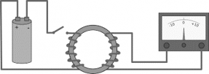
Faraday’s law of electromagnetic induction was the own discovery of two scientists Michael Faraday in the year 1831 and Joseph Henry in the year 1832. The first results from his experiments were released by Faraday. In his initial experiment, he found the principle of electromagnetic induction. In this, he rolled two metallic wire strips all across the iron ring. With this, he came to know the principle behind electromagnets. He believed that when there is the flow of current at one end of the wire, this stimulates to generate waves all across the ring and develops electrical power on the other side of the wire. This principle stood as a base for developing multiple experiments of electromagnetic induction. And this is the history behind the discovery of Faraday’s law. This article explains clearly the concepts of how Faraday law is operated, enhance of EMF in the coil, its laws, and applications.
What is Faraday’s Law?
Faraday’s law of electromagnetic induction is basically termed Faraday’s law. This is the fundamental principle of electromagnetism which foresees the concept that how EMF (Electromotive force) will be generated when there is the interaction of the electric current with a magnetic field. This scenario is termed electromagnetic induction.

Basic Principle Of Faradays Law
In the discovery of this law, one scenario of it which was transformer EMF was articulated later on as the Maxwell-Faraday equation. This signifies that Faraday’s law can be derived by using the Maxwell-Faraday equation which describes transformer EMF and through Lorentz where this states regarding motional EMF. Considering the integral form of Maxwell-Faraday, one can illustrate only transformer EMF, whereas considering an integral part of Faraday law illustrates both the motional and transformer EMF.
Faraday law is the one equation which states about two distinct phenomena which are motion EMF (which is developed by the magnetic force in the case of moving wire) and the transformer EMF (which is developed by the electrical force that happens because of the variation in a magnetic field). This is considered as the two phenomena for Faraday’s law.
Formula
The basic principle of Faraday law states that the EMF which is across the closed surface equals the negative variation in the magnetic flux in the closed path with respect to time rate. Here, the closed path is considered to be conductive. Consider that for a wire loop that is placed in the magnetic field has a magnetic flux ФB and the surface is of any and Σ is the boundary for the provided loop. As there will be movement in the wire loop, one has to consider Σ(t) for the provided surface. Now, the magnetic flux is represented as:
ФB = ʃʃΣt) B(t) . dA
Here, ‘dA’ is considered as the surface area element on the moving surface Σ(t), and ‘B’ is considered as the magnetic field, ‘B.dA’ presents the flux element around dA. In a simpler way, it can be defined as the magnetic flux across the wire loop will have a direct proportion related to the magnetic field lines which pass from the loop.
When there is a change in flux, B gets varied or else as the wire loop is changed or both, then as per Faraday’s principle wire loop gains EMF which is stated as the energy received from the unit amount of charge which has gone all across the loop. The equation was selected to have compatibility with the terms of special relativity. Similarly, this is the voltage which is calculated by cutting wire into pieces in order to form an open circuit and then connecting a voltmeter across the edges of the wire.
Faraday’s law defines that electromotive force is represented as the change in the magnetic flux which is shown as
Є = -(dФB/dt)
Here, ФB is termed as magnetic flux and є is the electromotive force. The path of the EMF is provided by Lenz’s principle. Faraday’s principle explains the relation between the variables’ paths and their magnitudes. Even though the relationship was not depicted clearly, it was known through the mathematical formula.
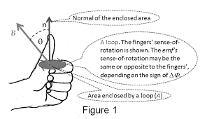
Through Faraday’s law, it is possible to know the path of the EMF without referring to Lenz’s law. For this, the left-hand rule will be helpful and the direction can be known as follows:

Left Hand Thumb Rule Faradays Law
- Line up the left-hand curved fingers with the loop.
- Stretch out your thumb finger and the direction of the thumb finger signifies the ‘n’ path which is general to the area that is surrounded by the loop
- Know the sign of ΔФB which is the variation in flux. Find the initial and last flux values corresponding to ‘n’ as signaled by the expanded thumb
- When the variation in flux ΔФB, represents positive value, then the curved fingers represents the path of EMF
- Whereas when the variation in flux ΔФB, represents a negative value, then the path of EMF will be in opposite direction to the curved fingers.
- In the case of tightly surrounded wire coil which consists of ‘N’ similar turns having similar ФB, then Faraday’s law defies that
Є = -N (dФB/dt)
Where ‘N’ corresponds to a total number of turns in the wire and ФB corresponds to magnetic flux across one loop.
And this is the detailed explanation of Faraday’s law formula.
Faraday’s Law of Electromagnetic Induction
There are mainly two laws in Faraday’s law of electromagnetic induction. The first one defines the induction of EMF in the moving conductor whereas the second one specifies the generated EMF in the conductor. Let us have an in the detailed look at both the laws.
Faraday’s First Law
Electromagnetic induction is the invention of extended series of experiments done by the scientists Henry and Faraday. With the results obtained from these experiments, Faraday came up with the end result that there is the induction of electromotive force in the coil when the magnetic flux through the coil is varied in relation to time. With this basic concept, Faraday’s first law was invented. This can be represented in the picture as shown below.

Changing Magnetic Field Intensity in CLosed Loop Faradays Law
So, when the conductor is kept in the changing magnetic field, there will be the induction of EMF. When the circuit where the conductor is placed is closed, then the generated current is termed as induced current.
Below are the ways to alter the intensity of the magnetic field in the closed-loop:
- By revolving the coil corresponding to the magnet
- By changing the coil either internal or external to the magnetic field
- By altering the location of the area where the magnetic field is placed
- By making coil and magnet either to away or to close.
Faraday’s Second Law
The electromotive force which is induced in the coil equals the rate of variation in the flux linkage. The flux is considered as the product of flux linked to the coil and the total number of turns present in the coil. The formula is given by
Є = -N (dФ/dt)
Where ‘N’ corresponds to a total number of turns in the wire, Ф corresponds to magnetic flux across one loop and ‘Є’ corresponds to magnetic flux.
The negative sign represents that the path of the induced electromotive force and variation in the path of magnetic fields have opposite directions. In addition to this, through Lenz’s principle also, electromagnetic induction can be known.
Experiment
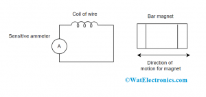
The main experiment that drives Faraday to introduce Faraday’s principle was not that much complicated. By using a few household equipments, the discovering of this law took place. Here we are using a cardboard tube that is shielded with wire in order to form a coil. For this arrangement, a voltmeter is connected through the coil, and the generated electromotive force is read as the magnet made to pass through the coil setup. The setup is shown below.
The observations that were made with this experiment are:
- When the magnet is at the constant position or placed close to the coil, there will be no voltage
- When the magnet initiates to move in the direction of the coil, there will be some voltage and this increases to the peak value when it comes to the middle point of the coil
- When the magnet starts to move away from the middle point, there will be a change in the sign of the calculated voltage
- When the magnet comes out and is far from the coil, then the calculated voltage in the reverse direction to the previous scenario of the magnet moving close to the coils.
With respect to magnet position and the calculated EMF, the graphical representation is shown as
These are the stable observations of Faraday’s law. Even though the constant magnet might generate a huge magnetic field, there will be null EMF that is induced due to the reason that flux across the coil will not get changed. When the magnet approaches the coil, the flux promptly enhances till the position of the magnet is internal to the coil. When it starts to pass over the coil, then the magnetic flux across the coil tends to decrease. As a result of this, induced EMF will get reversed.
Initial Experiments
As there are many experiments done by Faraday, the initial three were:
- In the 1st experiment, it was demonstrated that the magnetic field strength gets altered when the current is induced. By connecting the ammeter to this set-up, it gets deflected when the magnet approaches in the direction of the wire.
- In the 2nd one, he showed that the passage of current over the iron rod might form it as electromagnetic. He came to know that when there exists relative movement in between the coil and magnet, then induction of EMF takes place. When the magnet was revolved around the axis point, there will be no EMF. Whereas in the case when the magnet revolves across its own axis point, then the induced EMF will be generated. Because of this, there happens no deflection in the ammeter when the magnet is kept constant.
- And in the 3rd experiment, Faraday noted that the galvanometer shows no deflection and there is no induced EMF in the coil when the coil was placed in the constant magnetic field. The ammeter gets deflected in the reverse path when the magnet is moving far from the loop.
The above experimental observations were tabulated as:
| Magnet Position | Galvanometer Deflection |
| The magnet has no movement | The galvanometer shows no deflection |
| Magnet approaches towards the coil | Galvanometer deflection takes place in one way |
| Magnet is constant near to the coil | The galvanometer shows no deflection |
| The magnet moves far from the coil | Galvanometer deflection will be in the reverse direction |
| Magnet is constant far from the coil | The galvanometer shows no deflection |
Examples of Faraday’s Law
A permanent magnet that has a diameter of 10mm generated a field value of 100mT. The field falls away quickly with respect to distance and is very minimal which is 1 mm more from the boundary. When the magnet is moving at a speed of 1 meter/second across the coil with 100 turns and having a length of 1mm and diameter somewhat more than the magnet. Then what is the value of induced EMF?
Solution
1). In order to find the induced EMF, Faraday’s law can be employed. For this one has to be aware of flux change across the coil and how rapidly the variation takes place.
This can be initiated by independently observing the situations when the magnet’s position is in and out of the coil. As we know that the field reduced quickly, it can be thought that the flux becomes zero when the position of the magnets is out of the coil. As the coil is tightly coupled to the magnet, it was thought that the field position is orthogonal to the coil’s position and the flux is given by
Ф = BA
As the magnetic movement is at 1000 mm/sec, it was considered as internal to the 1mm length of coil for 1/1000 sec. By using Faraday’s law,
Є = -N (dФ/dt)
= -(100) [(100.10-3T)∏(5 . 10-3)2]/(1 * 10-3)
= 0.78 volts
2). Consider that a field is pointing in the forward direction having a steady strength of B = 5T and a square-shaped strand with one wired loop and length of the sides is 0.1m.
Solution
The area of the loop is A = 0.1 × 0.1 = 0.01 m2
As the square loop travels towards the field, at an ‘x’ direction having a speed of 0.02 m/sec. This signifies that for a certain time period of Δt = 5 sec, the loop will move from being totally out of the field to totally internal to it, and the normal to the field will be associated with the magnetic field at every time interval. This means that ϴ = 0.
ΔФ = B ΔA cos(ϴ)
= 5T × 0.01 ×cos(ϴ)
= 0.05 Wb
Increasing Induced EMF in the Coil
Below are the procedures explaining how to increase EMF induced in the coil
- By increasing the value of ‘N’ which means that by augmenting the coil turns, as per Faraday’s formula, it was clear that by increasing the coil turns, the induced electromotive force also gets enhanced.
- With the rise in strength of the magnetic field which is ‘B’ that surrounds the coil. As per statistical calculations, when the flux enhances, induced EMF will also be increased. And theoretically, when there is a passage of coil across the high magnetic field, there will be increased lines of force to divide and so EMF increases.
- When the relative movement speed in between the magnet and coil is increased when compared with its previous value, the coil will divide the flux lines more quickly and this generates more induced EMF.
Applications
Faraday law is the most crucial and fundamental law in the concept of electromagnetism. This principle has applications across many industries and domains. A few of the applications of faraday’s law are:
The operation of power transformers is dependent on faraday’s law
- The main functionality of the electrical generator is based on the mutual induction principle of faraday’s law
- We all know that induction cooker are the devices which are found in every house these days. This device also functions based on the concept of mutual induction. When there is the passage of current across the copper wired coil which is present at bottom of the cooking vessel, it generates a varying magnetic field. This varying or altering magnetic field induces electromotive force and so the current generates in the vessel and with this heat production takes place in the device.
- An electromagnetic flowmeter is a device that is employed for the velocity calculation of some fluids. When there is the application of a magnetic field in the electrically isolated pipe where the conducting fluids are present, then as per the principle of faraday’s law, there will be an induction of EMF. This EMF has direct proportion to the velocity of the fluid flow
- Maxwell’s equations are the great applications of faraday’s law. As per this law, variation in the magnetic field creates variation in the electric field and the reverse principle of this is applicable in Maxwell’s equations too.
- The most fascinating application of faraday’s law is traffic lights. Here, the lights use wired loops in order to find out the impact of the induced magnetic field. Beneath the road, the wire loops including AC current produce a varying magnetic field and when any vehicle moves over them, it created induced eddy currents in the vehicle. Through Lenz’s principle, these currents form a reverse magnetic field, which shows the effect on the current that is present in the original wired loop. This effect implies that a vehicle is present which triggers the traffic lights to change color accordingly.
- Applicable in musical devices such as electric violins and guitars and in many others.
Please refer to this link to know more about Gauss Law, Snell’s Law , Flux meter.
Please refer to this link to know more about Gauss Law MCQs, Biot Savarts Law MCQs.
Finally, this the detailed information about Faraday’s law. This article has provided clear and proper info on Faraday’s law working principle, experiments, laws of induction, applications, and examples. It is also more needed to know how things get related to Faraday’s law?