Potentiometers are simply termed as POTs and these are even called as variable resistors. The main purpose of a potentiometer is to vary the value of resistance in the circuit. Even these can be employed to vary volume, and dim and brightness of a light. There exist various types of potentiometers such as carbon POTs, wired POTs and plastic POTs. The one type which we are going to discuss today is “Digital Potentiometer”. So, let us discuss more on digital potentiometer definition, how it is designed, types, interfacing with Arduino and applications.
What is a Digital Potentiometer?
A digital potentiometer can be called with various names such as digipot, digital resistor and resistive digital-to-analog-converter. It is a digitally managed electronic device which functions in a similar way of potentiometer, but it is employed using digital switches and signals. In a mechanical type potentiometer, manual controls are used by a person to vary the resistance values. Whereas in digipot, it automatically adjusts its resistance based on the specified condition.
POTs are generally used to vary the value of resistance, but digipots adjust the resistance through digital inputs other than having a rotary wheel or physical slider such as in mechanical POT.
Design
In a digipot, the digital action is performed using a resistor ladder (chain of resistors connected in series). At each ladder step, there will be an electronic switch and only one switch of all switches will be closed at any time stamp. This closed switch helps us in knowing the position/location of the wiper and the ratio of resistance. This design of digital POT is considered as an illustration of linear taper. The total number of steps in this resistive ladder defines the resolution of the device. The below picture shows the digital potentiometer circuit diagram in ladder design. The digital resistors are regulated through up/down signals or by protocols like SPI and I2C.
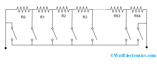
Digital POT Circuit In Resistor Ladder Design
Digipots are ICs where some of the devices have non-volatile memory and some have no on-boarding memory. The non-volatile memory recalls the resistance setting of the potentiometer. Whereas in the condition on no on-boarding memory, the starting point of the wiper is usually at middle position. As because digipots are small in size, multiple digital potentiometers can be considered in a single chip.
The below tabular column shows the bit count and corresponding step values.
| Bits | 10 | 9 | 8 | 7 | 6 | 5 |
| Number of Steps | 1024 | 512 | 256 | 128 | 64 | 32 |
The usual tolerance value in a digital POT is 20%, but these days’ tolerance below of 1% are easily available.
Digital Potentiometer Working Principle
In order to know the working of a digital POT device, its architecture has to be known. As the functionality of the device is only regulation of resistance, the architecture can be easily understood. There are mainly three components in the device which are:
- Chain of resistors
- Memory unit
- Control and Interfacing unit
Chain of Resistors
The digital potentiometers are constructed by connecting multiple resistors in a series format in such a way that they form a ladder structure. Every step in the ladder includes a switch which has connection with the potentiometer’s output. The device resistance is known by the total number of steps which means that higher resistance corresponds to more number of steps.
To calculate the number of steps, the bit value of the digital POT is considered. For instance, when there are ‘N’ bits, there are 2N steps.
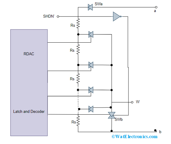
Series Of Resistors
So, when the bits are 5, the total number of steps are 25 = 32
Memory Unit
We know that digital devices may comprise of memory unit in order to perform its activities, in the same way as a digipot is digital device it also consists a memory unit. Most of the devices hold volatile memory unit which are used while the operation of the device and this memory unit does not store any previous data once the device is shut down. Therefore, many digital potentiometers initiate from first step onwards when they are switched ON or restarted. Whereas few digipots are also interfaced with microcontrollers or FPGAs so that last position is stored.
These days’ digital potentiometers are built where they have non-volatile memory unit and also capable of storing last position so that the previous position can be retained after the device is shut down.
Control and Interfacing Unit
This section is the crucial part in the device and this is the section which is not present in conventional type of potentiometer. Here, the signal is provided from microcontroller such as Arduino in order to adjust the resistance of the digipot. In every potentiometer there exists either synchronous or asynchronous series bus acting as interface and few digital POTs function by using front panelled switches or control logic.
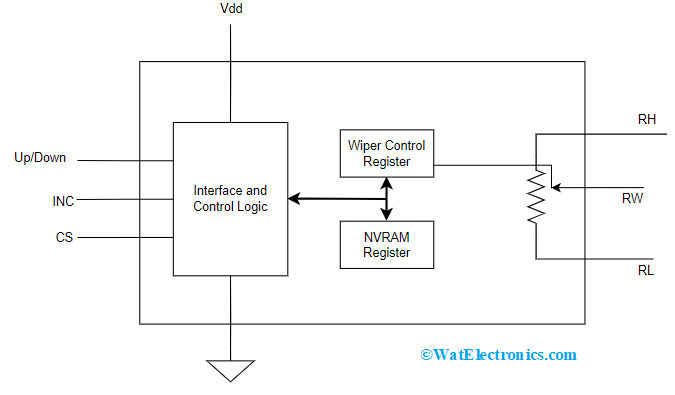
Control And Interface Unit
The best employed asynchronous bus is used to communicated information on the UP/Down counter. The above picture depicts the digipot having an increment/decrement interface. This bus has three signals which are:
- Chip Select (CS) – When CS is enabled, it functions as address input for many of the digipots.
- Up/Down Signal – When Up/Down is enabled, the potentiometer’s wiper will be adjusted up and down so that the digital POTs resistance gets increased or decreased.
- Increment (INC) – With the INC signal, the wiper can be adjusted at each falling edge of the INC signal.
The digital potentiometer can be interfaced either with I2C or SPI peripherals.
Interfacing with Arduino
This section explains interfacing a digital potentiometer with X9C103S with Arduino. The X9C103S is a digipot device where its resistance can be varied using a microcontroller. It has 3 pin output and consists of 99 resistance components and the last resistor can be regulated through a 3-wired interface. The X9C103S consists of 8 pins and the pinout description can be explained as follows:
- Vcc – A 5V power supply
- CS – It is chip select signal which is active LOW
- VH – It is high voltage pin
- VL – It is low voltage pin
- GND – Ground pin
- INC – Command for changing the resistor
- VW – Voltage wiper acts as voltage output for the variable wiper contact
- U/D – It is up down varying resistor
The below picture and code for Arduino connection with X9C103S are shown as follows:
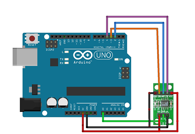
Digital Potentiometer Interface With Arduino
#include <DigiPotX9C103S.h>
Digital_POT potentiometer(2,3,4);
void setup() {
serial.begin(9600);
}
void loop() {
serial.println(“Initiating”);
for (int i=0; i<100; i++) {
potentiometer.increase(1);
serial.println(analog_Read(A0));
delay(20);
}
for (int i=0; i<100; i++) {
potentiometer.decrease(1);
serial.println(analog_Read(A0));
delay(20);
}
}
Types of Digital Potentiometer
Here are the few types of digital POT devices which are explained as follows:
Digipot with NVM (Non-Volatile Memory)
Few of the NVM type digipots are AD5245 and AD5246. Here, the settings are lost when the power is removed from the device. In order to store the desired setting, a non-volatile on chip memory device is required. Whereas, there are also few volatile digipots having a power on preset feature.
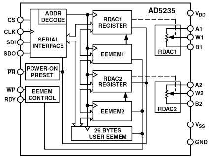
Non Volatile Memory Digital Potentiometer
As per the block diagram, when any modifications are done to RDAC register, the new setting values are stored in the E2MEM. Later when the system power is ON, automatically data gets transmitted to the RDAC register. The EEMEM even be recovered via direct programming and preset pin controlling. With the commands of linear step increment/decrement, the RDAC settings can be moved UP/Down by only one step at an instance.
In order to get logarithmic variations in the wiper settings, a right/left bit shift command alters the level either by +6 or -6 dB steps.
One Time programmable Digipot
The AD5172 is a dual channel one time programmable digipot having 256 positions. In order to gain memory of the resistance setting activity, this device use fuse link technology.
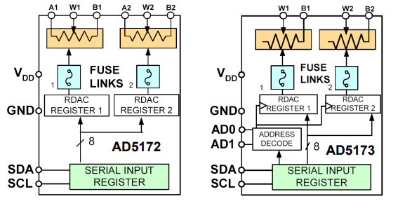
OTP Digital POT
The AD5172 device is programmed with a 2 wired I2C synced digital control. This permits for infinite adjustments in before the resistance value is permanently adjusted. When the OTP is activated, a command of permanent fuse blown is transmitted after recognizing the final value, so that wiper position is locked at the specified setting.
This device has an exclusive temporary OTP overwriting feature which permits for more adjustments if required. With this unique feature, the AD5172 is used in multiple active control applications having user defined presets.
The calibration of digital potentiometer can be achieved with OTP type of digipot where it calibrates the DC bias point of the RF power amplifier and the calibration can be programmed with no requirement any external controlling devices.
Digital Potentiometer VS DAC
This section explains on the differences between a digital potentiometer and digital-to-analog converter.
| Digipot (Digital Potentiometer) | DAC (Digital to Analog Converter) |
| A digital pot might consist of 1024 wiper taps which is similar to a DAC having 10 bit resolution | DACs are available with resolutions of either 24 bits or more than 24 bits |
| Digipots are used for supporting fairly slow signals | DAC devices can be able to generate an pass high speed signals |
| Employed in either fixed or slowly changing voltage generators | DACs are employed for RF and high speed purposes |
| In order to use digital POTs for DDS applications, these are unsuitable as because of lengthy settling time and minimal updation rate | Fast digital to analog converters that employed in DDS applications accepts digital inputs in the form of parallel words |
| The DNL (differential nonlinearity) is > -1, and the output is always monotonic | The DNL (differential nonlinearity) is < -1, and the output is not monotonic. DACs ensure monotonic output when the output is either = -1 or > -1 |
| The output impedance is higher and alters depending on the setting of wiper | The output impedance is minimal and correspondingly constant. |
| As digital POTs consists of up/down pulses, only few pins are enough and these are easily available in minimal packages | Slow DAC’s converters are available in small packages, whereas fast DACs consists of parallel pins and so obtainable in larger packages. |
| Digital POT can function as variable resistor when one of the resistors end is connected with digipot wiper. | Voltage-output type of DACs cannot be employed as resistors, whereas current-output DACs can function as variable resistors. |
Applications
In today’s electronic systems, there are extremely endless applications of the digital potentiometer. A few of those are:
Computers – Used as programmable power supply devices, set-points for temperature regulation, and battery chargers.
Consumer purpose – Electronic volume controlling and PDA backlight tunings.
Automotive industry – Used for calibration of sensors, regulation of instrumentation and actuators and adjustments in the navigation displays.
Optical industry – Wavelength controlling, used in optical attenuators, laser bias current tunings, and laser modulation current tunings.
Digital POTs are also for various general applications like voltage to current conversion devices, DACs, programmable filters and gain amplifiers.
What is the difference between digital potentiometers and analog potentiometers?
Analog potentiometers have a continuous range of resistance, while digital potentiometers have only two possible states: on or off. Digital potentiometers are also more precise than analog potentiometers.
What are the advantages of using a digital potentiometer over other types of pots?
A: The main advantage of using a digital pot is that you can use it with an Arduino or Raspberry Pi without needing any additional components. This makes it ideal for projects involving those devices!
How do you connect a digital potentiometer to an Arduino or Raspberry Pi?
A: You’ll need to add two wires to your pinout for each pot you want to use—one for connecting it up to ground and one for connecting it up to power. Then connect one end of each wire to one side of the pot’s wiper terminal and the other end of each wire to the appropriate power or ground pin on your device.
Please refer to this link for Ladder Logic.
Please refer to this link for Potentiometer MCQs, Ladder Logic MCQs.
Can you use a digital potentiometer to measure voltage?
Yes, you can use a digital potentiometer to measure voltage. However, you will need an ADC (Analog-to-Digital Converter) to convert the output of your digital pot into a number.
On the whole, this is all about the digipots. This article has provided clear points on digital potentiometer working, its circuit, types, comparison with DAC & applications. Furthermore, to know what are the limitations of digital potentiometer?