A transistor is the most significant three terminal electronic component which plays a key role as a building block of many integrated circuits. Generally, these are classified into three types; BJT (Bipolar Junction Transistors), JFET (Junction Field Effect Transistors), and MOSFET (Metal Semiconductor Field Effect Transistors). Further, these are classified into sub-types based on the type of semiconductor used like; PNP BJT, NPN BJT, p-Channel MOSFET, and n-Channel MOSFET. There are two main uses of transistors switches and amplifiers. This article discusses an overview of the BF494 transistor, pinout, specifications, circuit, working, and applications.
What is a BF494 Transistor?
BF494 is a medium frequency NPN transistor available in a SOT54 and TO-92 plastic package, used to switch or amplify electronic signals as well as electrical power. These transistor terminals are made with semiconductor material used for connecting to a circuit. This transistor is used within low voltage low current applications, TV receivers, radio, FM tuners, mixer-oscillators, and low noise AM IF amplifiers within AM or FM receivers.
The current supply throughout another pair of terminals can be controlled with an applied voltage (or) current to one terminal pair of transistors. Generally, a transistor magnifies a signal due to the higher regulated power as compared to the controlling power.
While looking for a suitable transistor for your application based on a few factors, it is very important to look into a few points on How to Select a Transistor.
Pin Configuration:
The pin configuration of the BF494 transistor is shown below. This transistor normally includes three terminals emitter, base, and collector which are discussed below.
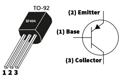
BF494 Transistor Pin Configuration
- Pin-1 (Base): This is a middle terminal of the transistor, used to activate the transistor. This terminal is thin & dope lightly.
- Pin-2 (Emitter): It is also known as negative lead transistor which is moderately sized & heavily doped.
- Pin-3 (Collector): It is the positive lead of the transistor. Its size is larger as compared to the emitter & is doped moderately.
Features & Specifications:
The features and specifications of the BF494 transistor include the following.
- It is a bipolar junction transistor.
- It is available in a TO-92-3 package or case.
- The mounting style is Through Hole.
- Transistor polarity is NPN.
- It has a single configuration.
- The maximum collector-emitter voltage or VCEO is 20V.
- Collector to base voltage or VCBO is 30V.
- The emitter to base voltage or VEBO is 5V.
- The Max DC collector current is 30 mA.
- Power dissipation or Pd is 500 mW.
- Its operating temperature ranges from -55°C to +150°Centigrade.
- The minimum DC collector or base gain or hFE is 65.
- Maximum DC gain or hFE is 220.
Equivalent & Alternatives :
The equivalent BF494 transistors are; BC547, IRF540, 2N3707, etc. Complementary BF494 transistors are; 2N2222 or 2N3904.
Replacing a suitable transistor in any circuit based on requirement is very important. To know how to replace it, please refer to this; Replacing Transistors in Electronic Circuits: Factors and Considerations.
FM Transmitter with Two Transistors
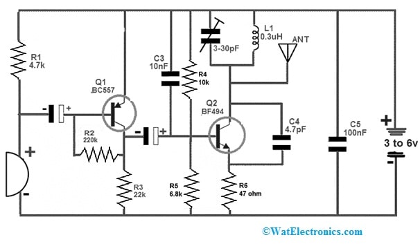
A simple FM Transmitter circuit using two transistors is shown below. This circuit functions very efficiently in close or distant ranges. We already are familiar with that there are different methods to transmit the data. So, the data in FM (frequency modulation) is transferred by changing the carrier wave frequency. In addition, there are different methods to design this circuit as well. So, here we are designing an FM transmitter with two transistors. This circuit also needs very less external components which finally makes it reasonable.
The required components to make this simple FM transmitter circuit mainly include; two transistors like; BF494 & BC557, ceramic capacitors like; 4.7pF, 10nF, and 100nF, resistors like; 220KΩ, 4.7KΩ, 22KΩ, 6.8KΩ, 10KΩ and 47Ω, 3 to 6V battery, electrolytic capacitors like;4.7µF/16V and 10µF/16V, Trimmer or variable capacitor range from 3-30 to 5-50pF, MIC, 0.3uH inductor and antenna. So, connect this circuit as per the simple circuit given below.
FM Transmitter with Two Transistors
Working
The condenser microphone in the above FM transmitter circuit is used to provide the audio signal. Whenever the audio signal from the microphone changes the audio signal into an electrical then it penetrates the PNP transistor’s base terminal which enhances the signal amplitude. This signal gets amplified more with the help of a Q2 NPN transistor. Here, a tank circuit is formed with a capacitor & inductor to generate the carrier waves.
The variable capacitor in the circuit changes the resonant frequency (RF) for excellent modification. So the antenna is connected to the circuit to transmit the carrier waves. Finally, you can listen to the audio signal provided to this circuit at a close range on any of the radios. This FM transmitter circuit is used in car radios, handy audio devices, and many more.
Connecting a base resistor to the base terminal of the transistor is mandatory to avoid it being damaged. Please refer to this link for; Choosing Base Resistance for Transistors in Electronic Circuits.
Advantages and Disadvantages
The advantages of the BF494 transistor include the following.
- It is designed for low voltage low current applications.
- It is a versatile, potent, compact & indispensable natural component.
- It amplifies efficiently both RF and audio signals by providing flexible functionality without extreme power consumption.
- It is designed to resist varying environmental situations, ensuring reliable performance across various settings.
- This transistor has a simple and very efficient design.
- It is affordable and provides high-performance signal amplification without imposing excessive costs, rendering it a smart choice for a variety of electronic projects.
- It is easily integrated into electronic circuits.
- This transistor is compatible with a variety of electronic components.
- Furthermore, the versatility of the BF494 NPN Medium Frequency Transistor IC extends to educational contexts. So it serves as a valuable teaching tool for students learning about transistors and signal amplification.
The disadvantages of the BF494 transistor include the following.
- This is a low-current & low voltage NPN transistor.
- If the rated DC voltage is exceeded then it can lead to breakdown, overheating, or even permanent injury to the component.
- Its design is quite old and possibly out of favor due to new, better, and perhaps cheaper alternatives.
BF494 Transistor Applications
The applications of the BF494 transistor include the following.
- The BF494 is a semiconductor device that can amplify or switch electronic signals and electrical power.
- It is a general-purpose RF transistor, used in many applications like radio & TV receivers, FM tuners, low-noise AM mixer oscillators, and IF amplifiers within AM or FM receivers.
- These are used in remote control applications, HF applications within television receivers, etc.
- This transistor is used in a TV-to-FM converter circuit.
- This transistor is employed in FM modulation.
- It is utilized in a jammer circuit to produce signals at similar frequency bands like device signals to cause interference & transmission blocking.
Please refer to this link for the BF494 Transistor Datasheet.
Thus, this is an overview of the BF494 transistor, pinout, specifications, circuit, working, and applications. Thus, this is a NPN type of medium frequency transistor mainly designed to use in low voltage and low current applications. So this IC plays a pivotal role in the realm of electronics by actively shaping & enhancing a variety of applications. Here is a question for you, what is an IRF540 transistor?