Amplitude Modulation is not only the approach of modulating the signal, but there also exist many other kinds of modulation techniques. Frequency Modulation is one of the types of modulation. In the earlier days of communications, the necessary bandwidth for transmission of signals was not wide and even they do not hold the ability to reduce the interference signals. In such a scenario, frequency modulation was introduced but it was not much accurate compare with amplitude modulation. Then after, “Edwin Armstrong”, modified the intensity and bandwidth capacity of FM transmitters and this introduction enhanced its implementation to transmit a wide range of frequencies. So, let’s dive into the detailed concepts of frequency modulation, waveforms, and derivatives.
What is Frequency Modulation?
In general, Frequency Modulation is termed as modulating a continuous transmitting wave which has no intervals and holds the information. While as per the basic definition, it is defined as “A carrier signal which has no information varies its frequency in correspondence with the change in amplitude of the modulating signal”. The below pictures clearly depict the explanation of the above-stated definition.
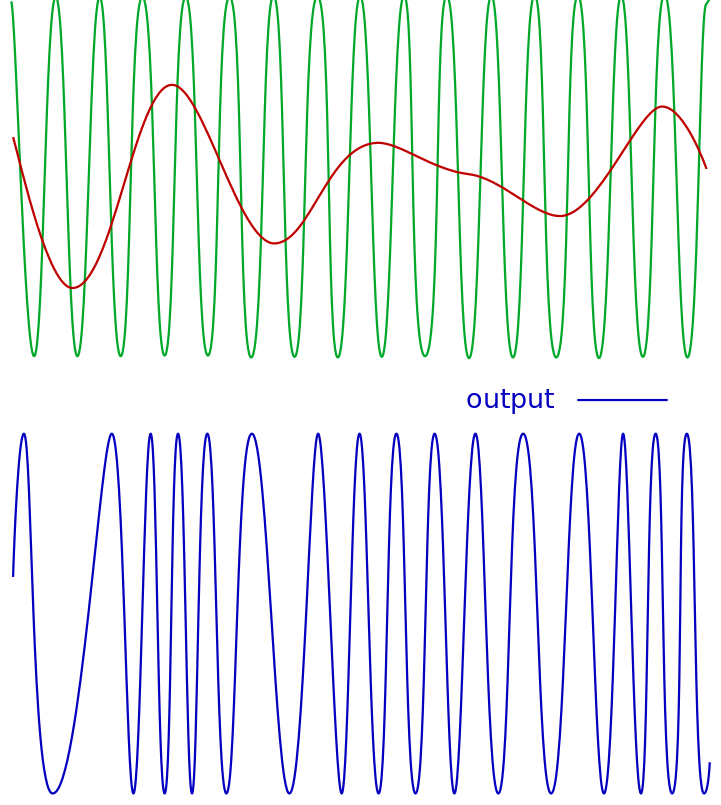
FM signal
The initial one is the message signal which holds certain information, while the second signal has no information and is called the carrier signal. The modulation of these waves results in an FM modulated wave. The FM modulated wave is more crucial as the frequency of this moves up and down based on the amplitude of the message signal and this change in frequency is represented in the form of kilohertz. For example, when the frequency deviation is 3 kHz up and down, then it is represented as ±3 kHz.
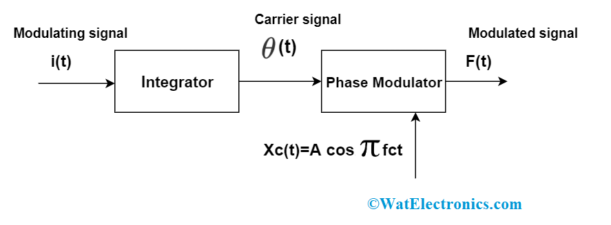
FM block diagram
Representation of Frequency Modulation
The modulating signal (input signal) is represented as
i(t) = β.sin (2∏fit)
The carrier signal is represented as
c(t) = Ac cos(2∏fct)
And in the expressions, Ac represents the amplitudes of the carrier signal while fi and fc are the frequencies of the two waves correspondingly.
Solving the two expressions, the modulated wave is represented as
F(t) = Ac. cos [2∏fct + β.sin (2∏fit)]
And, β represents the modulation index of the frequency-modulated wave
Modulation Index
The modulation index in FM is stated as the ratio of maximum carrier frequency deviation to the modulating signal (input message signal) frequency and it is denoted with β. The equation of modulation index is
Β = ∆f/fi
FM Bandwidth
Bandwidth is defined as the difference that is between maximum and minimum frequencies of them resultant frequency modulated signal. In amplitude modulation, it is easy to calculate the bandwidth as it is twice the frequency of the message signal. While in frequency modulation, bandwidth has to be considered in two cases where one is in narrowband and the other in a wide band. So, narrowband FM is stated as the circumstance where β is too minimal to make the whole terms after the initial two in the frequency modulation equation and that is negligible. It is represented as
FM bandwidth
β = ∆w/2∏fi which is almost less than 0.2 (where it could be a minimum 0.5 or more).
B.W is approximately 2wi
And in the case of wideband frequency modulation, the bandwidth is stated as to when a corresponding number of sidebands are with substantial amplitudes. And it is
B.W = 2∆w
Constant Bandwidth System in FM
Frequency modulation is considered to be a constant bandwidth system because of below reasons:
- The amplitude of the frequency-modulated wave remains to be constant
- The transmitted signal power all through the transmission stays as constant
- Unless the modulation frequency is increased, the bandwidth is not increased and remains constant
To be clear, let’s go with the below examples
- When ∆f = 75 kHz and fi = 200 Hz, then B.W = 2 [75 + (200/1000)] = 150.4 kHz
- When ∆f = 75 kHz and fi = 2000 Hz, then B.W = 2 [75 + (2000/1000)] = 154 kHz
- When ∆f = 75 kHz and fi = 20000 Hz, then B.W = 2 [75 + (20000/1000)] = 190 kHz
So, even when the frequency is increased from 20 to 20000, B.W lies only in the range of 150 to 190. Thus, because frequency modulation is stated to be a constant bandwidth system.
FM Spectrum Analysis
To analyze the frequency spectrum of the frequency modulated signal, we need to consider the sine wave modulation having the modulation frequency as fi.
Where i(t) = Ai cos (2∏fit)
This produces the FM modulated wave with the frequency of
Fi(t) = fc + kfAi Cos (2∏fit)
The above equation says that Fi moves up and down through a carrier frequency of fc over the specified range of ± kfAi. This is generally stated in correspondence with the modulated FM signal’s frequency variation and is
∆f = kfAi
And indicated that it is the maximum deviation in the swing on both the negative and positive sides of fc. Nd it is based on the amplitude of the message signal and not on fi.
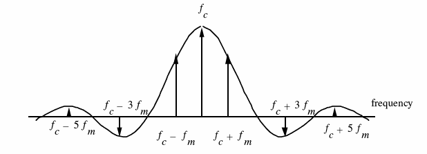
FM Spectrum Representations
Based on the values of the modulation index, the FM spectrum expands and the distance between sidebands increases. So, the sidebands move apart from the carrier signal by the frequencies of fc±fi, fc±2fi, fc±3fi and so like that. So, the spectrums are as below:
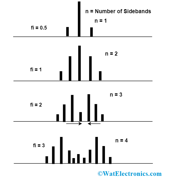
FM spectrum
The initial bands will contain maximum power (nearly 80%) and so these are considered to be significant sidebands. As per the rule of Carson’s, approximately 98% of the modulated signal power exists where the bandwidth is equal to the frequency variation and twice the frequency of the message signal.
Generation of FM signals
There are various approaches to generating FM signals. It means that frequency modulators are of many types and those generators are of:
- Varactor Diode Oscillator: Here, the generation of FM signal is possible by placing a varactor diode in the tuned circuit of the oscillator circuit or to make use of the varactor diode in the crystal oscillator circuit. But, when crystal oscillator, the modulated signals are with minimum frequency and it has to be amplified. So narrowband FM signals are only achievable through this approach.
- Phase-Locked Loop – This method is considered to be the best approach to generating FM signals. It is probably necessary to handle the constraints that are in the loop precisely but in the initial time itself, it generates accurate solutions.
Differences between AM and FM
At first, both amplitude and frequency modulations are used to transmit information through the technique of varying the carrier signal. Diagrammatically, the difference between these two are represented as:
As per the definition, in amplitude modulation, the amplitude of the modulating signal varies as per the carrier signal’s amplitude. The AM signals make use of lower frequencies to transmit information to long distances. While in frequency modulation, the frequency of the modulating signal varies as per the carrier signal’s amplitude. The bandwidth of the frequency-modulated signals is higher than that of AM modulated signals that help to transmit better quality voice signals.
|
Frequency Modulation |
Amplitude Modulation |
| FM has multiple numbers of sidebands | AM has only two sides.
|
| FM has a frequency range of 88 to 108 MHz | AM has a frequency range of 535 to 1705 MHz
|
| In FM, phase and amplitude stays as constant | In AM phase and frequency stays as constant
|
| The modulation index stays always more than 1 in FM | Modulation index always stays in the range of 0 to 1 in AM
|
| FM signals cannot transmit for small distances as these have an only minimal range | AM signals can transmit for long distances as these have greater ranges to transmit.
|
| FM modulated signal is more effective | AM modulated signal is not more effective |
| FM signals operate in the range of medium and high frequencies | AM signals operate in the range of very high and ultra-high frequencies |
| FM signals need a bandwidth of range 200 kHz | AM signals need less bandwidth of range 10 kHz
|
| FM signals are less effected to interferences and distortions | AM signals are more effected to interferences and distortions |
| No power is wasted as the whole power is carried by the message signal in FM | More power is wasted in AM
|
| In FM, when more signals are transmitted with similar frequency, the receiver receives only the strong signal and removes the weak signal | In AM when more signals are transmitted with similar frequency, all the transmitted signals are demodulated but causes interference
|
Advantages and Disadvantages of Frequency Modulation
Advantages
- The foremost benefit of FM is its resilience to any level of signal deviations. It is in the way that any level of signal deviations does not impose an effect on the audio, where the signal will not be at the level where the receiver will not cope. As a consequence of this, FM modulated signals are perfect for mobile and radio communications along with many other portable applications. Also, FM waves are not prone to any kind of distortions. So, FM signals are ideal for enhanced quality of broadcast transmissions.
- The other benefit is that it is likely to implement modulation even at the minimal stage of transmitters and it is not required to make use of the linear kind of amplification to enhance the signal power.
- It is even more possible to make use of the non-linear RF amplifiers to add up FM signals in a transmitter and these are of extremely effective than that of the linear ones necessary for signals having any kind of amplitude differences. This implies that for the provided power output, minimal battery power is necessary, and this shows that FM signals are more worthwhile for compact two-way kind of radio applications.
Disadvantages
Few of the disadvantages that are in FM signals are
- FM demodulators are somewhat complicated to construct, but not considered much as because radio integrated circuits are built up with internal demodulators in themselves.
- As FM signals are extended to infinity, in some cases they need filters to reduce the sideband’s extendibility. As because of this, some level of distortion is introduced because of filters. So, this is one of the indirect disadvantages of FM.
- FM signals have less spectral efficiency than compared with that of the other modulation techniques.
Please refer to this link to know more about Amplitude Modulation MCQs and Frequency Modulation MCQs
Applications
The applications of FM transmission include
- Seismic prospecting
- Magnetic tape recording
- Radar transmissions
- Radio broadcastings
- Telemetry
- Music synthesis
- Observation of EEG signals
FAQs
-
How is frequency modulation done?
FM is done through the process of transmitting a carrier signal with that of the message signal and this results in the generation of FM signal varying the signal frequency as per the amplitude of the message signal.
-
How is FM bandwidth calculated?
Using the formula of 2(∆f + fi), the bandwidth is calculated
-
What is the modulation index formula?
The formula of modulation index in FM is ∆f/fi
-
What is the frequency swing?
It is stated as the peak variation in between the minimum and maximum values of the instantaneous frequency.
-
What is the modulation coefficient?
The modulation rises and declines the voltage both above and below the certain value by a maximum quantity which is represented as Ea. The ratio of Ea/Ec is termed as the modulation coefficient (m).
Even there are disadvantages, frequency modulation can be widely used in many commercial and personal applications. Know more about the concepts of what are the other types and derivatives of frequency modulation?