A mono-bridged audio power amplifier or bridge-tied load is a type of audio amplifier configuration that mixes the two stereo amplifier channels into a mono channel. This results in very powerful amplifier channel that delivers double the output power of the amplifier used without bridging. Generally, amplifiers have two separate stereo and bridged mono power handling specifications. So, this is used most frequently for subwoofers. This article discusses an overview of a mono-bridged audio power amplifier IC like the LM4871 IC, its pin-out, features, specifications, and applications.
What is LM4871 IC?
The LM4871 IC is a mono-bridged audio power amplifier, available in MSOP, LLP, DIP and SO packages. This IC has features like thermal shutdown protection, external gain set, and unity-gain stability. Whenever this IC is powered with a 5V power supply then it has <10% THD.
The LM4871 IC has a power shut-down mode, where power can be saved by providing power to the shutdown terminal. This audio power amplifier IC’s shut-down mode value is normally 0.6 µA, and it generates high-power audio output. This amplifier chip bypasses the utilization of a large number of exterior components.
This mono-bridged audio power amplifier does not need bootstrap capacitors, snubber networks, or output coupling capacitors. So it ensures unity-gain stability and is suited ideally for low-power portable systems that require minimum weight and volume. These ICs are designed mainly to provide high-fidelity audio output and high power thus they can be utilized in desktop computers, low-voltage audio systems, and portable computers.
LM4871 IC Working
The LM4871 mono bridged audio power amplifier IC works with a 5V power supply to deliver continuous 3Watts average power into a 3Ω load with < 10% THD. So this audio power amplifier amplifies and outputs voltage variations between two input pins:
LM4871 IC includes a micro-power shutdown mode which activates by providing VDD to the shutdown pin. So this mode helps in conserving power, especially within portable applications This IC generates high power audio output. It avoids the use of a large number of exterior components. So it doesn’t use snubber circuits, bootstrap capacitors, and coupling capacitors for LM4871 IC operation.
Operating Modes
LM4871 audio power amplifier works in three operating modes micro-power shutdown, BTL, and bridged mode which are explained below.
- The micropower shutdown mode of this IC is activated whenever high logic is provided to the SHUTDOWN pin. So it is designed mainly to save power within portable applications.
- The LM4871 IC can switch to BTL mode.
- The LM4871 IC includes two op-amps within a single package that allows for mainly bridged mode operation.
LM4871 IC Pin Configuration:
The pin configuration of LM4871 IC is shown below. So this IC includes 8 pins where each pin and its functionality are discussed below.
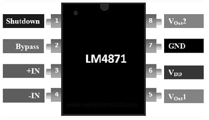
LM4871 IC Pin Configuration
- Pin-1 (Shutdown): This pin enables shutdown mode whenever VDD is provided to this pin
- Pinp-2 (Bypass): This pin is used for high power supply rejection and low noise performance.
- Pin-3 (Non-Inverting Input (+IN)): It is a noninverting pin of the audio amplifier IC.
- Pin-4 (Inverting Input (-IN)): It is the inverting input pin of the audio amplifier IC.
- Pin-5 (Vout-1): It is the first output pin of an audio power amplifier IC.
- Pin-6 (VDD): It is a positive voltage supply terminal of the IC.
- Pin-7 (GND): It is a ground terminal of the IC.
- Pin-8 (Vout2): It is the second output pin of an audio power amplifier IC.
Features & Specifications:
The features and specifications of LM4871 IC include the following.
- LM4871 is a mono-bridged audio power amplifier IC.
- This IC is available in MSOP, LLP, DIP, and SO packages.
- It includes 8 pins.
- Its voltage supply is 5.5 V.
- The quiescent power supply current is 10 mA.
- Its shutdown current is 2µA.
- Its output offset voltage is 50 mV.
- Output power 2.38 Watts.
- Its THD (Total Harmonic Distortion) + Noise is 0.13 or 0.25%.
- Its PSRR or power supply rejection ratio is 60 dB.
- The supply temperature is -65 to +150 °C.
- Junction temperature is 150°C.
Equivalent & Alternatives
Equivalent LM4871 ICs are; 8002A, 8002B and TDA2050. Its alternatives audio amplifier ICs are; TDA2030, LM386, LM1875, IC6283, AD620, JRC4558, etc.
5Volts USB Audio Amplifier Circuit with LM4871 IC
5Volts USB audio amplifier circuit with LM4871 IC is shown below. These are designed mainly to work through a 5V supply using a computer USB socket. This 3-watt simple amplifier circuit can be powered from a 5V USB port of a computer directly to drive an 8-ohm 3-watt speaker.
The required components to make this circuit mainly include; resistors like 40 K ohm, and 100 K ohm, capacitors like 0.39uF ceramic and 1uF/16V Tantalum, LM4871 IC, and 8 ohm 3-watt speaker. Connect this circuit as per the diagram shown below.
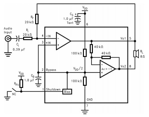
5Volts USB Audio Amplifier Circuit with LM4871 IC
The inverting input resistor like Ri is used to set the closed loop gain with Rf. This resistor can also implement an HPF function through Ci at frequency fC = 1/(2π RiCi).
The input coupling capacitor Ci is connected to allow audio AC frequency across the i/p pins and block DC. So this capacitor allows an HPF in conjunction through Ri at frequency fC = 1/(2π RiCi).
The feedback resistance Rf fixes the closed loop gain through Ri.
Here, Cs works like a supply bypass capacitor to provide ripple filtering mainly for the power supply.
Cb is connected as the bypass pin capacitor which enforces filtering mainly for half-supply.
Working
The LM4871 IC in the above circuit has two op-amps internally, so the first op-amp gain can be externally managed whereas the next op-amp is connected internally through an inverting unity gain. Here, the first amplifier’s closed-loop gain can be determined by properly choosing the Rf/Ri ratio values while the same has been fixed mainly for the second amplifier internally throughout two 40K resistors.
Here first amplifier’s output can be configured to the input of the second amplifier by allowing two amplifiers to produce signals with the same values, even though these may be 180 degrees out of phase. Thus this can result in the differential gain of IC that is; AVD = 2*(Rf /Ri). A bridged mode for any amplifier can be set up by driving the load via a couple of Vo1 & Vo2 outputs.
The amplifier in this mode has a different operating principle as compared to the usual single-ended amplifiers which include one end of the load connected through the ground line. A bridged mode amplifier circuit works with superior efficiency as compared to a single-ended amplifier because the load is switched within a push-pull way, allowing a double voltage swing for every alternate frequency pulse.
Actually, this allows the load to generate 4 times the power in equal circumstances (or) specifications. So the ability to attain such enhanced power allows the audio amplifier to work exclusive of a current limiter stage and undesirable clipping. Thus, these circuits are used in desktop computers, portable computers, and low-voltage audio systems.
Advantages & Disadvantages
The advantages of LM4871 IC include the following.
- The LM4871 IC has a micro-power shutdown mode feature that saves power whenever it is not in use.
- This IC operates on low supply voltages which range from 2.0V to 5.5V.
- It doesn’t need output coupling capacitors, snubber networks, or bootstrap capacitors.
- It has an external gain configuration ability, thermal shutdown protection, and stable unity gain.
- Its pin configuration is well-matched with the LM4861 IC.
- This IC is well-suited for low-power portable systems that need minimum weight & volume.
The disadvantages of LM4871 IC include the following.
- LM4871 IC is tolerant of combinations of external components, consideration of component values should be used to increase the quality of the overall system.
- These ICs need a few external electronic components.
- They operate with low voltage supply only which ranges from 2.0V to 5.5V.
- The LM4871 IC must be utilized within low gain configurations to reduce THD+N values & the S/N ratio.
- This amplifier IC combines two amplifier channels into one, thus it has one amplifier channel only.
- Bridging can finely affect sound quality, particularly when utilizing stereo audio sources.
- The power increase can be limited through current limitations.
Applications
The applications of LM4871 IC include the following.
- The LM4871 ICs are perfect for mobile phones, PDAs, and portable communication devices wherever they give good-quality audio output.
- The efficient power usage of this IC makes it to use in battery-operated gadgets.
- These are used in sound bars, audio peripherals, and portable speakers.
- It is applicable for low-voltage applications as it doesn’t need snubber networks, bootstrap capacitors, or output capacitors.
- It has a less power consumption shutdown mode which activates by driving simply the shutdown pin through logic high.
- This IC is designed to be used in audio applications within portable communication devices and mobile phones.
- It can be utilized as a headphone amp, microphone preamplifier, speaker amp, and volume control amplifier IC.
- The application areas of LM4871 ICs involve desktops, portable computers, guitar amplifiers, low-voltage audio systems, Hi-Fi devices, talking toys, radio wave transmitters, keyboard amplifiers, etc.
Please refer to this link for the LM4871 IC Datasheet.
Thus, this is an overview of the LM4871 mono bridged audio power amplifier IC, pin configuration, features, specifications, circuit, working, pros, cons, and its uses. This IC delivers a 3W continuous average power supply into a 3Ω load whenever it is powered with a 5V power supply. So it is well suited to low-power portable systems and low-voltage applications. It includes a micro-power shutdown mode to save power, unity-gain stability, and thermal shutdown protection. This amplifier chip can also include an external gain set & can switch easily to BTL mode. Here is a question for you, what is LM1875 IC?