Formerly, automobile manufacturers used to connect various electronic devices in automobiles using a number of wires through point-to-point connections. This resulted in huge wire connections which were very expensive and bulky. Later, this complicated wiring system got replaced by dedicated wiring that enhanced communication speed between devices and provided high integrity, and was named as controller area network. The CAN was first developed by Bosch in the year 1985 for in-vehicle networking. Using CAN protocol, many other protocols are standardized which are CANopen and DeviceNet. Now, we are going to discuss completely on CAN protocol definition, architecture, its block diagram, analyzer, advantages, and disadvantages.
Introduction to Controller Area Network
Controller Area Network (CAN Bus) is defined as a message-based protocol that was designed to provide reliable communication between multiple Electronic Control Units (ECUs). It is a serial networking technology that was mainly developed for European cars but gained popularity in the industrial automotive domain and many other applications too.
Through a CAN bus, various microcontrollers and devices can have real-time communication without the need for a hosting computer. It does not need any kind of addressing schemas because the protocol itself has unique identifiers providing the data about the urgency and significance of the transmitted message.
The CAN protocol basics are explained as follows:
CAN bus is considered a half-duplex, high speed, and two wired networking system which holds great dominance over traditional networking systems like RS232. When compared with consistency and functionality, CAN buses are most effective and provide enhanced broadcasting between ECUs.
As IP/TCP protocols are developed for the transmission of large size of information, the CAN bus was developed for real-time scenarios having a baud rate of 1Mbit/sec. This eliminates the issues of slow error recoveries, inappropriate error detections, and lengthy reaction timings.
The below picture shows how CAN bus communication is established by comparing it without the CAN bus.
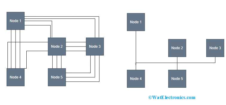
With CAN vs Without CAN
Block Diagram
In the CAN protocol block diagram, the CAN bus employs a multi-master bus pattern for the transmission of frames between various nodes and it can be able to manage error handling scenarios. The core allows the user to establish a reliable and economic connection between multiple ECUs. The CAN protocol seems to be a memory-mapped I/O device for the host processors having the access to CAN core in handling either the frames transmission or reception.
In the picture CAN CTRL can be easily integrated and used and it consists of the required number of independently programmable acceptance filters, programmable interrupts, and common processor interfacing (APB, AMBA, or AHB-Lite). This networking protocol implements a flexible buffering system which helps in fine-tuning the core size as per the necessity of different applications.
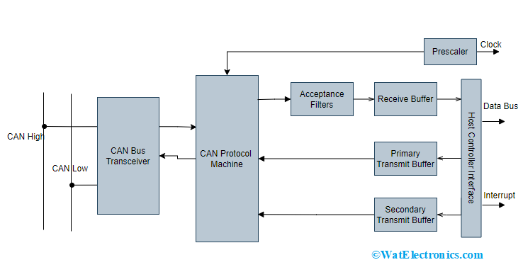
CAN Protocol Block Diagram
Using the APB interface in the functioning of the CAN bus allows for minimal power consumption and eliminates the complexity of interfacing. Whereas AHB-Lite assists in providing high performance and good clock frequency systems.
Using the number of receive buffers is based on synthesis-time configuration. There are two kinds of transmission buffers which are PTB and STB (Primary Transmission Buffer and Secondary Transmission Buffer). The PTB buffer holds high priority and STB has low priority. The primary transmission buffer holds the ability to store one message and the number of buffer slots to be used in the secondary transmission buffer is synthesis time configurable. In the priority mode, the transmission buffer functions in First-In, First-Out approach.
CAN Layered Architecture
The CAN communication protocol ISO 11898 defines how data is communicated between multiple devices in the network. The physical medium which is defined by the physical layer in the architecture is responsible for establishing actual communication.
The ISO 11898 defines the data-link and physical layer as the CAN communication.
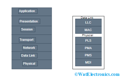
Layered Architecture
Data – Link layer – This layer is used for establishing data transmission between multiple nodes. Even holds the responsibility for identifying and removing the errors that take place at the physical layer. This layer again consists of two sub-layers which are of:
MAC – Medium Access Control – This layer describes how various devices present in the network can receive accessibility to the medium. Here, data signaling, error identification, message encapsulation and decapsulation take place.
LLC – Logical Link Control – This layer offers logic for the data-link layer because it manages flow controlling, multiplexing, acceptance filtering, recovery handling, and overload warnings.
Physical Layer – This layer is useful in raw information transmission. It outlines the properties for the parameters like timing, information rate levels, voltage ratings, and connector. This ISO 11898 has mainly three portions.
PCS – Physical Coding Sublayer – It observes that when the functional connection has been established and this layer is defined in Fast Ethernet, 10 Gigabit Ethernet, and gigabit Ethernet standards. It performs encoding and decoding of information, scrambling and descrambling, and rate variance compensation.
PMA – Physical Medium Attachment – It executes the framing of data and is responsible for transmitting and receiving high-speed information based on the structure of the transceiver channel. It also performs octet synchronization.
PMD – Physical Medium Dependent – It describes the particulars of transmission and reception of every bit that takes place on the physical medium. It also has a transceiver required for the medium.
MDI – Medium Dependent Interface – It defines the interface for the medium in the network which is useful in carrying the transmission.
Working Principle and Data Transmission
In the CAN protocol working principle, every CAN network operation should include a device that supports the CAN protocol, where it transmits data in the form of packets which are termed CAN frames. Each CAN frame is included with arbitration/message ID, remote, data, and error frames.
As discussed the CAN protocol is a multi-master network protocol and it employs the approach of CSMA/CDMA with message priority. Before the transmission of any message, the node verifies whether it the busy or not.
When we consider Ethernet networking protocol, in the process of collision detection both the transmission nodes stop transmitting where they have to wait for a certain period to transmit again. This creates higher sensitivity for heavier loads. And in the CAN protocol, this problem is resolved using the arbitration approach.
The arbitration process helps in prioritizing the CAN bus owner during the situations of two nodes transmitting the message at the same time.
Consider an example that ECU 1 with the identifier of 0x234 and ECU2 with identifier 0x352. These two nodes transmit messages at the same time. So, to know the process of how arbitration works, let us understand the below section.
When we observe the 3rd bit of both ECUs, ECU1 is ‘0’ and ECU2 is ‘1’. As CAN follows wired-AND logic, the CAN bus has a final value of ‘0’. Each node that sends its message to CAN-bus read it again to analyze the proper transmission which is termed Bit Monitoring.
When the message that is read is not some as that of the transmitted message then it shows a transmission error and stops transmitting. In a similar way, ECU2 does not know what the transmission is as the final value becomes ‘0’ at the CAN bus whereas ECU1 continues to transmit.
The Data field corresponds to the data format that is transmitted to the CAN bus and is available in two formats. Those are standard CAN and extended CAN. The standard CAN is of 11-bit length and the extended CAN is of 29-bit length.
Standard CAN – The format in standard CAN is explained as below:

Standard CAN Data Format
SOF (Start of Frame) – It specifies that a new data frame is started in the CAN network which is of 1-bit length.
Identifier – It establishes the data frame priority which means the least binary value holds a high priority.
RTR (Remote Transmission Request) – It explains the type of frame which is either remote or data frame. This bit holds prominence when data is necessary from another node. Its length is 1-bit.
Controlling Field – It consists of user-specified functions.
- IDE (Identifier Extension) – Here, the foremost IDE bit specifies that it is a standard CAN identifier whereas the lowering IDE bit specifies it is an extended CAN identifier.
- DLC (Data Length Code) – It specifies the data field’s length which is 4 bits.
- Data field – It can transmit application information of up to 64 bits.
CRC (Cyclic Redundancy Check) – It is of 15-bit length and this is helpful in error detection at the time of transmission. At the time of transmission and reception of the data frame, the CRC is calculated, then the results are computed. When the results are not the same, it creates an error.
ACK (Acknowledgement) – It is of 2-bit length which is acknowledgment and delimiter bits. When compared with other protocols, CAN does not require any distinct packet for acknowledgment, whereas other protocols need distinct packets for an acknowledgment after the reception of entire packets.
EOD (End of Frame) – This 7-bit field indicates that the frame has ended and stops bit-stuffing which means it indicates a stuffing error when the field was dominant.
Extended CAN – The format in extended CAN is explained below:

Extended Data Format in CAN Protocol
In the extended CAN format, there will three additional bits than that of standard CAN.
SRR (Substitute Remote Request) – This bit substitutes the RTR bit as a placeholder.
IDE (Identifier Extension) – A recessive bit in IDE specifies that the network contains additional identifier bits to be followed.
r1 – Next to the RTR and r0 bits, there is one more reserve bit which is ahead of the DLC bit.
Data Transmission
A single CAN network consists of various nodes. Let us consider three nodes CAN network node X, node Y, and node Z. Each CAN node comprises three components.
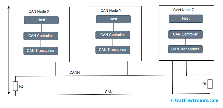
Data Transmission In CAN Protocol
Host – This is the node that can be either a microprocessor/microcontroller that performs particular tasks by running a few applications. This analyzes the content in the received message and decides which message should be transmitted later.
CAN Controller – The functionality of the CAN controller is to deal with the communication functions defined by the CAN protocol. The controller is even responsible for initiating the transmission and reception of CAN messages.
CAN Transceiver – The transceiver transforms the data signal into a stream of data received from the CAN bus.
To establish communication between the nodes, an unshielded twisted pair cable is employed which is termed as CAN bus. It has two lines which are CANH (CAN High Line) and CANL (CAN Low Line). The transmission of data happens because of the varying voltage levels provided to the CANH and CANL lines. As differential voltage is applied, we can know either logic HIGH or logic LOW bits are transmitted. Here, HIGH logic in CAN is termed as recessive and logic LOW in CAN network is termed as dominant.
For example, when we supply 2.5 volts for both the lines, then the differential voltage is ‘0’. This is considered as a logic HIGH by the CAN transceiver which means that the CAN bus is in a recessive state.
When we supply 3.5 volts and 1.5 volts for CANH and CANL lines, then the differential voltage is ‘2 volts’. This is considered as logic LOW by the CAN transceiver which means that the CAN bus is in a dominant state. In this state, the bus moves to the dominant state, and then it becomes difficult to get back to the recessive state by other nodes.
As per the above truth tables, we can observe that the dominant state overwrites the recessive state. When there is the simultaneous transmission of dominant and recessive bits, then the CAN bus is in the dominant state, whereas the recessive state happens when all the nodes transmit recessive bits which is the AND logic.
Types of CAN Protocol
There are mainly four CAN protocol types which are:
High Speed CAN – It has a transmission rate of 1M bits.
Low Speed CAN – It is also termed a fault tolerance type and has a transmission rate of 125 K bauds/second. This CAN type initiates communication at the time of any error.
Software Selectable CAN – This has 2 ports where every port can be employed for high, low speeds or else single wired CAN.
Single Wire CAN – From CAN device to CAN network, this type has one wire and the transmission rate is of 88.3 bauds/second. It even provides a high voltage pulse for waking up the inactive device.
Differences between CAN and other protocols
The below tabular column shows the comparison between CAN protocol vs I2C and CAN protocol vs Ethernet.
| CAN | I2C |
| It follows asynchronous communication | It follows synchronous communication |
| It is two wired protocol with CANH and CANL signals | It is two wired protocol with SCL and SDL signals |
| CAN protocol transmission happens lover long distances and communication takes place between the host controller and other devices | I2C protocol communicates only to short distances and communication happens between two ICs in the same circuit |
| This protocol is developed by Bosch | This protocol is developed by Philips |
| This interface is placed within two circuit board | This interface is placed within the circuit board |
| Using differential signal technology, the transfer of data takes place between two nodes | Using the help of two wires, data transfer can happen between two nodes |
CAN vs Ethernet
| CAN | Ethernet |
| CAN protocol has ISO 11898 standardization | Ethernet protocol has IEE 802.3 standardization |
| It follows bus topology | It follows a star topology |
| It has a maximum transmission speed of 1Gbits/second | It has a maximum transmission speed of 1Mbits/second |
| For the maximum speed transmission, the maximum cable length required is 40 meters | The maximum cable length required is 15 meters |
| It can allow transmission with copper, twisted pair, and single unshielded cables | It can allow transmission with copper and twisted pair cables |
CAN Bus Analyzer
The analyzer tool is useful in debugging a high-speed CAN bus network that supports ISO 11898-2 and CAN 2.0b. Either by using a screw terminal interface or DB9 connector, this tool can be connected to the CAN network and this tool has the features to trace a group of CAN messages transmitted between nodes and has a log file that would help the developer or tester to analyze the data transmitted between devices.
It can be able to transmit messages either in a single or periodic way to the CAN bus which helps in the CAN network testing. With all these unique features, the CAN analyzer can be employed in multiple industries such as industrial, automotive, medical, and marine.
Arduino in CAN Network Protocol
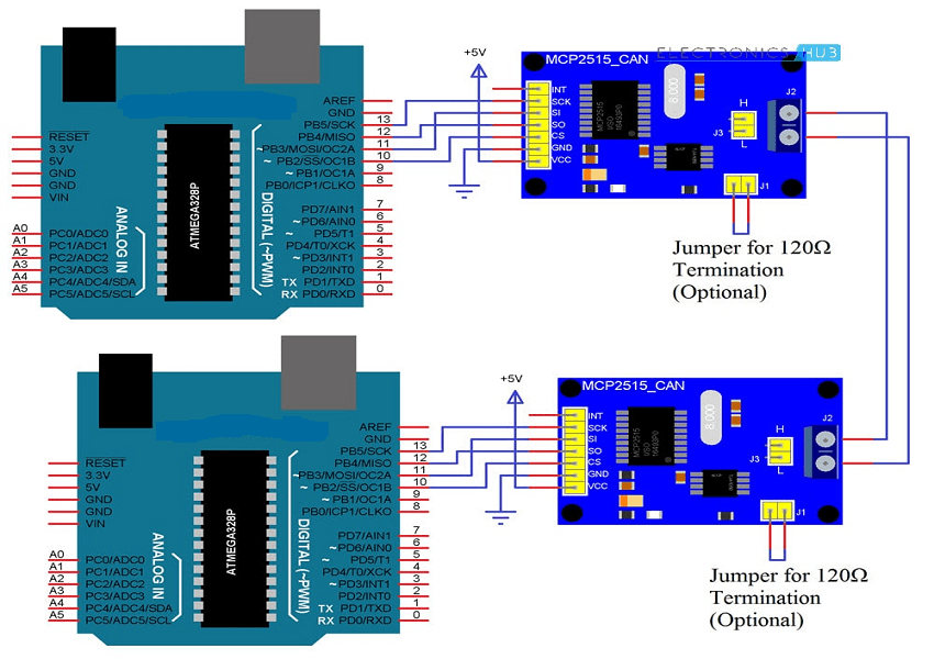
For an Arduino there is no inbuilt CAN port, so to establish communication between CAN and Arduino, a CAN module is used which is MCP2515. This is a simple CAN Bus controller that supports the CAN protocol version of 2.0B with a transmission rate of 1Mbps. Let us in detail how MCP2515 is interfaced with Arduino.
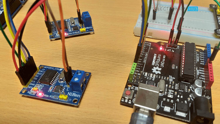
The below picture illustrates the circuit diagram.
In order to connect the CAN controller with any microcontroller, it takes the support of SPI. So, connect the SCK, MISO (SO), MOSI (SI), and CS pins of the MCP2515 module with the similar pins of Arduino. To know how to connect an SPI module with Arduino please refer to this link. SPI communication with Arduino. Make two connections in such a way one functions as a transmitter and the other as a receiver. Now, establish the communication between two MCP2515 modules by connecting their CANH and CANL pins correspondingly.
The code for transmission and reception of data is explained below:
Transmission Code:
#include <SPI.h>
#include <mcp_can.h>
const int SPI_CS_Pin = 10;
int LED_HIGH = 1;
int LED_LOW = 0;
MCP_CAN CAN(SPI_CS_Pin);
void setup()
{
Serial.begin(115200);
while (CAN_OK != CAN.begin(CAN_500KBPS))
{
Serial.println(“Failure of CAN Bus initiation”);
delay(100);
}
Serial.println(“CAN BUS Shield Init OK!”);
}
unsigned char stmp[8] = {LED_HIGH, 1, 2, 3, LED_LOW, 5, 6, 7};
void loop()
{
Serial.println(“In loop”);
CAN.sendMsgBuf(0x43, 0, 8, stmp);
delay(1000);
}
Receiver Code:
#include <SPI.h>
#include “mcp_can.h”
const int SPI_CS_Pin = 10;
const int LED_Pin = 2;
boolean LED_ON = 1;
MCP_CAN CAN(SPI_CS_Pin);
void setup()
{
Serial.begin(115200);
pinMode(LED_Pin,Output);
while (CAN_OK != CAN.begin(CAN_500KBPS))
{
Serial.println(“Failure of CAN Bus initiation “);
delay(100);
}
Serial.println(“CAN BUS Init OK!”);
}
void loop()
{
unsigned char Length = 0;
unsigned char buf[8];
if(CAN_MSG_AVAIL == CAN.checkReceive())
{
CAN.readMsgBuf(&Length, buf);
unsigned long CAN_Id = CAN.getCAN_Id();
Serial.println(“—————————–“);
Serial.print(“Data from ID: 0x”);
Serial.println(CAN_Id, HEX);
for(int i = 0; i<Length; i++)
{
Serial.print(buf[i]);
Serial.print(“\t”);
if(LED_ON && i==0)
{
digitalWrite(LED_Pin, buf[i]);
LED_ON = 0;
delay(500);
}
else if((!(LED_ON)) && i==4)
{
digitalWrite(LED_Pin, buf[i]);
LED_ON = 1;
}
}
Serial.println();
}
}
Advantages and Disadvantages
This section explains on CAN protocol’s advantages and disadvantages.
Advantages
- As the CAN bus is the distributed control system, complex wiring can be eliminated.
- It can be used in various electrical environments having no problems.
- CAN network protocol provides error-free data transmission where every node is tested at the time of transmission.
- No traffic congestion as message transmission takes place based on priority.
- It can be used with both multi-master and multicast features.
- It has the ability to detect acknowledgment errors and stuffing errors.
- It offers a high-speed rate.
- It is simple, reliable, and available at minimal pricing.
Disadvantages
- It operates at a limited length.
- There might be signal integrity problems.
- Sometimes, there occurs unnecessary communication between the nodes.
- It can be extendable only up to 64 nodes.
- For the software development and management of the device, high costs are the problem.
Please refer to this link for CAN Protocol MCQs
CAN Protocol Applications
The primary development of CAN protocol was to resolve communication problems in automobiles. Later, it got employed in many other domains for various purposes and those are as below:
- Used for navigation and aviator electronic devices.
- Employed in sports cameras.
- Aircraft engine management systems like pumps, linear actuators, and fuel systems.
- Mechanical controlling and industrial automation domain.
So, this is all about the communication of CAN protocol. This article has explained CAN protocol basics, working principles, interfacing with Arduino, Types, architecture, and Applications. Also, know what are the examples of CAN protocol?

