Step-down voltage regulators are electronic devices that change a lower voltage to a constant output voltage. These regulators are also called DC-DC step-down switching regulators or buck converters which decrease an input voltage to low and regulated voltage very efficiently compared to linear voltage regulators. These regulators utilize a switch to separate a DC voltage and then use an inductor and capacitor to smooth the outcomes. So these are used to handle electrical fluctuations in electronic devices. This IC is highly efficient with 80% to 95% efficiencies and also have low quiescent current. Example of step-down voltage regulators mainly include; LM2678, LM2575, TPS5450, LM22678, L4976, LM3578A, LT10742IC, etc. Thus, this article discusses an overview of LM2574 IC, pinout, features, specifications, and applications.
What is LM2574 IC?
The LM2574 IC is a 3.3V 0.5A monolithic step-down voltage regulator that provides different active functions for a buck-switching regulator. It is capable of driving 0.5Amps load with outstanding line & load regulation. So this regulator IC is available in the 3.3, 5.0, 12, and 15 V fixed output voltage & an adjustable output version. This IC is simple to use and uses less number of components. It has frequency compensation & a fixed-frequency oscillator internally. The LM2574 IC provides a high-efficiency replacement mainly for the popular three-terminal linear regulator.
This voltage regulator is designed to reduce the number of exterior components to shorten the design of the power supply. Since the LM2574 IC is an SMPS, its efficiency is much higher as compared to three-terminal popular linear regulators, particularly with higher input voltages. So the power dissipated by this regulator IC is very low in many cases, so a heat sink is not required (or) its size could be decreased dramatically.
Working
The LM2574 step-down switching voltage regulator IC works by transmitting energy from input to output with a power switch, diode, or inductor. It is an SMPS that is more efficient as compared to linear regulators, particularly at high input voltages. This IC is available in 3.3V, 5V &12V fixed output voltages and also an adjustable version from 1.23V to 37V output voltage range. The LM2574 IC supplies 0.5A current while maintaining load regulation & good line.
These ICs are highly efficient, thus heat sinks are generally not necessary. It has a cycle-by-cycle current limiting & thermal shutdown feature to defend against errors. This IC has an outside shutdown connection to choose standby or operating modes. It has a 52kHz fixed frequency oscillator internally with ±10% guaranteed tolerance.
Pin Configuration:
The pin configuration of LM2574 IC is shown below. This IC includes 8 pins which are discussed below.
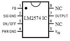
LM2574 IC Pin Configuration
- Pin-1 (FB): It is a feedback pin of IC, used to measure & adjust the o/p voltage.
- Pin-2 (SIG GND): It is a signal GND pin of the IC, It is connected commonly to the common GND terminal of the circuit to provide a constant reference potential for the operation of the regulator.
- Pin-3 (ON/OFF): It is an ON/OFF pin of the voltage regulator IC which turns ON or OFF with logic levels. To turn ON the voltage regulator, the ON/OFF pin needs to pull below a threshold voltage. Similarly, it needs to be pulled above the threshold voltage to turn it OFF.
- Pin-4 (PWR GND): It is a power GND pin of the voltage regulator IC which provides ground. This pin is neutral mainly for both the input & output.
- Pin-5 (Vin): It is an input voltage pin that provides a voltage supply to this pin.
- Pin-6 & 8 (NC): It is a No Connection pin of the IC.
- Pin-7 (OUT): It is an output pin of the voltage regulator IC.
Features and Specifications:
The features and specifications of LM2574 IC include the following.
- Its output versions are; 3.3V, 5V, 12V & adjustable.
- The input voltage ranges from 4.75 to 40 V.
- It needs four external components only.
- These are highly efficient.
- This IC uses standard inductors.
- It has TTL shutdown capability and low-power standby mode.
- It has a fixed 52 kHz frequency internal oscillator.
- These are Pb−Free devices with high efficiency.
- It has a maximum of 1.23V to 37V ±4% over line & load conditions.
- This IC has a current limit and thermal shutdown protection.
- Its typical low-power standby mode is below 200µA.
Equivalents & Alternatives
Equivalent to LM2574 IC is TPS560430 IC. Alternative LM2574 ICs are; LM2575, LM2576, LM2577, LM2578, TPS5450, L4976, LM22678, LT10742IC, LM3578A, etc.
5V Low-Noise DC Converter Circuit with LM2574 IC
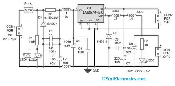
The 5V low-noise DC converter circuit with LM2574 IC is shown below. This circuit is used for converting DC voltages to use in embedded systems. Generally, linear regulator usage can be found within an AC-DC adaptor but it needs a large heat sink to dissolve thermal power. So here is a low-noise, low-cost, and simple DC-DC converter circuit designed with LM2574 IC.
The required components to make this 5V low-noise dc converter circuit with LM2574 IC mainly include; a 12V power supply, LM2574 IC, 1N4007 rectifier diode, 1N5819 Schottky diode, 5mm LEDs, resistors like 1.5-kilo ohm, 0.1 ohm, 1-kilo ohm, capacitors like 1nF and 100 nF ceramic disk, electrolytic capacitors like 100 uF 63V, 220 uF 16V and 100 uF16V, CON1 to CON3 two pin terminal connector, 1A fuse, 10uF and 330 uH inductors. So connect this circuit as per the diagram shown below.
5V Low-Noise DC Converter Circuit with LM2574 IC
Working
The 5V DC low-noise converter circuit using LM2574 IC is shown above. So this circuit is designed with 12V DC input which uses an input filter as well as a diode to protect reverse voltage. LM2574 IC is available with fixed outputs (3.3V, 5V, 12V & 15V) & adjustable versions (1.23V to 37V). Here the input voltage across CON1 can be adjusted (or) unregulated from 7Volts to 40Volts.
Its actual input mainly depends on input capacitors & rectifier diodes’ voltage ratings. So LED1 & LED2 show the existence of input voltages through polarity indication. So LED1 will be ON whenever the input voltage polarity is negative and LED2 will be ON whenever the input voltage polarity is positive.
Fuse & Capacitors
The F1 fuse in the circuit is resettable and chosen based on the current abilities of the voltage source & D1 protection diode. For single use, we can replace the F1 fuse with a 0.5A simple fuse & D1 (1N540X/1N1400X) with a suitable transil. Here D1 can be chosen based on the maximum input voltage as well as the fuse rating. Thus, the R2 Resistor is used for monitoring the converter’s input current which may produce noise. So, an input LC filter is utilized to hold back the noise.
The C1 to C3 capacitors and L1 to L2 inductors are significant in the LC filter. Here inductors are wound on a similar core which is utilized to avoid input ripples & noise. These inductors are chosen based on the highest output current.
Here, C4 & C5 capacitors provide extra filtering for the switching IC. The o/p voltage is 5V & o/p current is up to 0.5Amps. So this regulator’s switching frequency is around 52kHz and is higher as compared to audible range frequency. So here, D2, L3, C6 & C7 in the circuit change pulses from LM2574 IC to 5V DC voltage through some ripples, which are obtainable at the CON2 output connector. Additionally, filtering can be finished with C8 & L4. So this output is made accessible at CON3. Here LED3 in the circuit shows the existence of 5v production DC across CON2 & CON3 connectors.
Advantages & Disadvantages
The advantages of LM2574 IC include the following.
- The LM2574 IC is highly efficient.
- It has a wide input voltage that ranges from 4.75 to 40 V.
- This IC has cycle-by-cycle current limiting and thermal shutdown for protection in fault conditions.
- These voltage regulators are simple to use, versatile, and low-power-based switching regulators.
- This IC has a low-power standby mode.
- These are reliable & inexpensive.
- These ICs use readily available standard inductors.
- These are Pb-free devices.
- It simplifies the switch-mode power supply design.
- It supplies 0.5A current while maintaining outstanding line & load regulation.
- They don’t need a heat sink due to less power dissipation.
The disadvantages of LM2574 IC include the following.
- These regulators can be injured if they stress beyond the highest ratings listed within the maximum ratings.
- Exceeding the maximum limits of this can damage the reliability of the device.
- They cannot work at a higher voltage.
- They are delicate & have a limited rating of power.
- It has limited in-built ESD protection.
- These ICs have limited power rating.
LM2574 IC Applications
The applications of LM2574 IC include the following.
- The LM2574 monolithic voltage regulator IC can be utilized to design a buck converter, called a step-down switching regulator.
- The LM2574 regulators are suited ideally for easy and convenient step−down switching design.
- These high-efficiency regulators replace three-terminal linear regulators.
- In addition, LM2574 IC can also be used as an efficient pre-regulator, on-card switching regulator, positive-to-negative converter, negative step-up converter, and power supply mainly for battery chargers.
- This switching regulator IC converts an i/p voltage to a regulated o/p voltage with PWM techniques.
Please refer to this link for the LM2574 IC Datasheet.
- What is the output voltage range of LM2574?
The adjustable version supports outputs from 1.23V to 37V. - Does LM2574 need a heat sink?
In most low-current designs, no heat sink is needed due to high efficiency. - What is the switching frequency of LM2574?
It operates at a fixed 52kHz frequency.
4. What is the difference between LM2574 and LM2575?
Both are buck regulators; LM2575 can supply 1A, while LM2574 supplies 0.5A.
Thus, this is an overview of LM2574 IC, pinout, features, specifications, circuit, working, pros, cons, and its applications. So this is a fixed (or) adjustable switching voltage regulator with ±4% guaranteed o/p voltage tolerance for particular input & load conditions. Thus this IC can also have an output switch through thermal shutdown & cycle-by-cycle current limiting. The LM2574 is an SMPS so it is very efficient as compared to higher input voltage three-terminal linear regulators. Thus, this regulator needs minimal external components and its standby current is below 200µA. Here is a question for you, what is TPS560430 IC?