The BC148 is a small signal transistor from the NPN family and is a good choice mainly for audiophiles. This transistor is well known because of its outstanding musical characteristics and technical specifications it is perfect for high-fidelity audio. This transistor provides high current gain, it has less noise, which gives excellent sound quality and its compact size will make it easy to incorporate into different electronic applications. This article discusses an overview of the BC148 transistor, pinout, specifications & its applications.
What is BC148 Transistor?
The BC148 is an NPN-type silicon transistor, available in a SOT25 case. This transistor includes three terminals such as an emitter, base, and collector, and three layers P, N & P. Here a P-layer or positively charged layer in between two N-layers or negatively charged layers. This transistor is used in electronic modules for mainly audio & radio. It can also used as either an amplifier or a switch. So this transistor as an amplifier can turn a tiny electrical signal into a better & very powerful one. Similarly, when this transistor is used as a switch, then it allows current to be supplied throughout at specific times only.
This transistor has 100 mA current and its BE (Base-Emitter) voltage is 6V thus you have to supply this voltage across the emitter & base terminals of the transistor to induce current at a base terminal into the transistor.
While looking for a suitable transistor for your application based on a few factors, it is very important to look into a few points on How to Select a Transistor.
Working
BC148 is an NPN transistor thus the emitter and collector terminals will be Reverse-biased or left open. Whenever the base terminal is held at GND and will be forward biased or closed when a signal is given to the base terminal. This transistor gain value ranges from 100 and 300 which determines the transistor’s amplification capacity.
Whenever this transistor is completely biased, it allows maximum current to supply across the emitter & collector terminals, known as the saturation region. The typical voltage permitted across the VCE or VEB could be 20V and 5V respectively. Once the base current is detached, then the transistor will become completely off, so this stage is known as the Cut-off Region and the Base Emitter voltage could be around 6V.
Pin Configuration:
The pin configuration of the BC148 Transistor is shown below. This transistor includes three terminals which are discussed below. This transistor includes an arrow symbol from the base terminal to the emitter direction which means the current supplies from the collector to the emitter terminal.
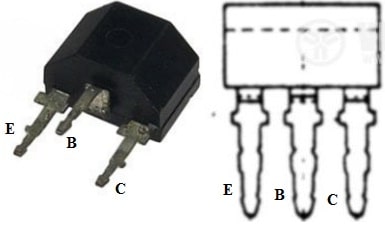
BC148 Transistor Pin Configuration
- Pin-1 (Collector): Current flows in throughout this terminal.
- Pin- 2 (Base): This terminal controls the transistor biasing.
- Pin-3 (Emitter): Current drains out throughout this terminal.
Features & Specifications
The features and specifications of the BC148 transistor include the following.
- It is a BJT-type transistor.
- This transistor polarity is NPN.
- The material of the transistor is Silicon.
- It is available in the SOT25 case.
- Its max collector power dissipation or PC is 0.25W.
- Collector to base voltage maximum or VCB is 30Volts.
- Its maximum collector-to-emitter voltage or VCE is 20V.
- The collector’s current maximum or IC is 0.2A.
- Its collector capacitance or CC is 5pF.
- The transition frequency or FT is 150MHz.
- The forward current transfer ratio or hFE value is 110.
- The maximum emitter to base voltage or VEB is 5V.
- Its maximum operating junction temperature or TJ is 125°C.
Equivalent & Complementary Transistors
Equivalent BC148 transistors are; BC184, BC548, BC557, BC547, BC549C, 2N4401 or 2N3904. The complementary BC148 Transistor is the BC158 PNP transistor.
Replacing a suitable transistor in any circuit based on requirement is very important. To know how to replace it, please refer to this; Replacing Transistors in Electronic Circuits: Factors and Considerations.
How to use BC148 Transistor Safely in a Circuit for a Long Time?
To use the BC148 transistor securely for a long time in a circuit, it is significant to not operate it under its operating voltage. A suitable base resistor must be used and not provide more than the 100mA load. Always keep this transistor in its operating temperature range thus it should not be operated in environments > 150 degrees Celsius. Ensure correct biasing by applying a requited voltage to the BE junction of the transistor to forward bias it. Always verify its pin configuration before connecting it to any electronic circuit.
Light Sensor Circuit with BC148 Transistor
The light sensor circuit using the BC148 transistor is very simple to design which triggers a relay whenever a Light incident on LDR is above threshold. The required components to make this simple circuit mainly include; a BC148 transistor, light-dependent resistor or LDR & 6V relay through a protection diode. Connect this circuit as per the diagram shown below.
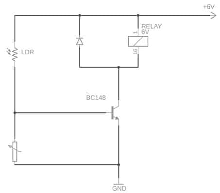
Light Sensor with BC148 Transistor
Working
This circuit works very simply because it uses less components within it only. This light sensor circuit uses a single transistor which switches ON the relay whenever light drops on LDR. So, LDR exhibits less resistance whenever light drops on it & high resistance whenever very low intense light drops on it or it is obstructed.
In the above circuit, the potentiometer is used to change the sensitivity as well as set a light threshold for this light sensor circuit. A relay in this circuit is used to turn on any appliances or devices whenever the light goes beyond the set threshold. A diode is used along with the relay to protect other electronic components from the high voltage generated whenever a relay coil is turned off.
Once light drops on the sensor, its resistance will be low so the transistor goes into saturation state & turns ON the relay circuit. Whenever the light obstructs the sensor then it provides a high resistance to the current supply. So the potentiometer shorts the base terminal of the transistor to the GND & it is cut off. Therefore this makes the relay off so that we can notice the light falling on any object.
Touch Switch Circuit with 4069 IC
A simple touch switch circuit using 4069 IC is designed to drive relays, LEDs, and many more throughout a buffer transistor stage. This circuit can also be designed with any CMOS inverter chip although here we have used 4069 IC preferably. This IC can be run off any DC-regulated supply from +3Volts to +15Volts.
The required components to make this touch switch mainly include; touch plates, 4069 ICs, BC148 transistor, RL1 relay, push button switch, IN4148 diodes and R* is 100Ω. Connect this simple circuit as per the diagram shown below.
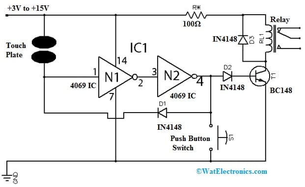
Touch Switch Circuit with 4069 IC
Working
This touch switch works as; whenever there is no connection between the touch contacts pair within the circuit, then the N1 IC input is low & its output will be high so it makes the N2 input high & output low. Thus, there is no current supply throughout D1 & D2 diodes within this state.
Whenever a finger links the contacts, then the input of N1 becomes high & its output will be low which makes the N2 output high. Here, the D1 diode conducts and provides a return pulse to the N1 input to effectively latch the touch circuit within the ON state. So the N2 output is fed throughout a buffer transistor state & turns ON an LED, relay, etc.
The R resistor in the circuit is used to reduce the load on the battery as well as the transistor. This value must be about 100 ohms mainly for a 9V power supply. So the resistor value for other voltage supplies can be derived by using the following relationship.
R = (1000 * Vcc) / Im
Here, ‘Im’ is the current rating of relay within mA. From the power supply, about 100mA must be drawn, and a 100mA relay with 12V appropriate voltage may be chosen for use.
Connecting a base resistor to the base terminal of the transistor is mandatory to avoid it being damaged. So, please refer to this link for; Choosing Base Resistance for Transistors in Electronic Circuits.
Advantages & Disadvantages
The advantages of BC148 Transistor include the following.
- The BC148 transistor is ideal for audiophiles and high-fidelity audio applications,
- It has excellent technical specifications and musical characteristics.
- This transistor provides low noise and high current gain for excellent sound quality.
- Its size is compact thus; it can integrate easily into different electronic components.
- It is a reliable choice for attaining top-notch audio performance.
The disadvantages of BC148 Transistor include the following.
- These are small and sensitive.
- It has less input impedance.
- It depends mainly on temperature.
- Faults easily cannot be found because of its small size.
- It is very hard to substitute with a new transistor by unsoldering
- It does not work efficiently like a mechanical electrical switch or a relay.
BC148 Transistor Applications
The applications of BC148 transistors include the following.
- BC148 transistor can be used as either an amplifier or a switch.
- It is used with different driver modules like LED driver, Relay driver, and many more.
- It is used in amplifier modules like signal Amplifiers, Audio amplifiers, etc.
- This transistor can be used in the Darlington pair.
- It is a small signal transistor, so it is perfect for high-fidelity audio applications like building (or) improving audio systems.
- These are used in various electronic devices which include; televisions, mobile phones, industrial control & radio transmitters.
- It is used for general-purpose small signal amplification.
- It is a small signal transistor, so it is perfect for audiophiles.
- This transistor is an ideal choice mainly for high-fidelity audio applications because of its technical specifications and excellent musical characteristics.
Please refer to this link for the BC148 Transistor Datasheet.
Thus, this is an overview of the BC148 Transistor, pinout, features, specifications, circuit, working, and its uses. So this transistor can be used as a switch (or) as an amplifier within different applications. This transistor’s Base-Emitter voltage is 6Volts which can be provided across the base & emitter terminals of the transistor to induce a base current into the transistor. Here is a question for you, what is a BC548 transistor?