2SC9018 is an NPN-type high-frequency silicon epitaxial transistor, manufactured by KEC. This transistor includes three terminals (E, B & C) and three layers (two N-layers and one P-layer). The majority of charge carriers in this transistor are electrons. So it is a reliable and versatile transistor, used commonly in different electronic circuits for signal processing and amplification purposes. This article discusses an overview of the 2SC9018 Transistor, pinout, specifications, circuit, working, and its applications.
What is a 2SC9018 Transistor?
The 2SC9018 is an NPN small signal bipolar junction transistor used commonly in radio frequency amplifiers, audio amplifier circuits & other low power-based applications. This transistor is housed within a small plastic package like a TO-92 package including three leads used for simple mounting on a circuit board. Thus, this transistor has 50mA of a maximum collector current and 20V of a maximum collector-emitter voltage. This transistor has a high gain and low noise figure which makes it suitable for use within low noise amplifiers & other HF applications.
The construction of this transistor can be done with two n-type material regions with a p-type material layer which is arranged in between two N-layers. This transistor includes two PN junctions; the emitter-base junction & the collector-base junction. These transistors are used for amplifying current or voltage within analog circuits & also to switch current or voltage within digital circuits. This transistor is used typically in high-frequency amplifier applications, so it is compatible to use in circuits that require high gain at UHF or VHF frequencies.
While looking for a suitable transistor for your application based on a few factors, it is very important to look into a few points on How to Select a Transistor.
2SC9018 Transistor Pin Configuration:
The pin configuration of the 2SC9018 Transistor is shown below which includes three terminals like a BJT; emitter, base, and collector which are discussed below. The arrow symbol on this transistor indicates the conventional current direction.
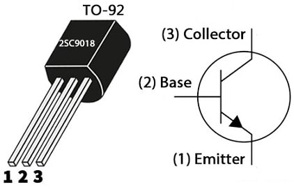
2SC9018 Transistor Pin Configuration
- Pin-1 (Emitter): This terminal is moderately sized and doped heavily which supplies electrons to the base terminal. As the name suggests, it emits electrons.
- Pin-2 (Base): This is the thin and lightly doped terminal arranged between the emitter & collector. This terminal supplies the charge carriers from the emitter terminal to the collector.
- Pin-3 (Collector): This is the larger and moderately doped terminal as compared to the emitter & base. This terminal gathers the charge carriers that are transmitted by the emitter through the base terminal.
Features & Specifications:
The features and specifications of the 2SC9018 transistor include the following.
- It is an NPN-type transistor.
- This transistor material is Silicon.
- The type of transistor is BJT.
- It is available in the TO92 package.
- Its collector-to-emitter voltage or Vceo is 15V.
- Collector to base voltage or Vcbo is 30V.
- Collector current or Ic is 0.05A.
- Its hfe ranges from 28 to 198 at 1mA.
- Its power dissipation or Ptot is 400mW.
- The current gain bandwidth is 1100MHz.
- Collector power dissipation or Pc maximum is 0.4 Watts.
- The collector to base voltage or Vcb maximum is 30 V.
- Collector to emitter voltage or |Vce| is 15 V
- The emitter to base voltage or |Veb| is 5 V.
- Its maximum collector current or |Ic max| is 0.05 Amps.
- Its operating junction temperature or Tj maximum is 150 °C.
- Its transition frequency or ft is 1100 MHz.
- Collector capacitance or Cc is 1.3 pF.
- Its minimum forward current transfer ratio or hFE is 28.
Equivalents & Replacement Transistors
Equivalent and replacement of 2SC9018 transistors are; KTC9018, SS9018, 2SC9018D, 2SC9018F, 2SC9018E, JE9018E and JE9018D. The complementary 2SC9018 NPN transistor is the SS9015 PNP transistor.
Replacing a suitable transistor in any circuit based on requirement is very important. To know how to replace it, please refer to this; Replacing Transistors in Electronic Circuits: Factors and Considerations.
How to Long Run 2SC9018 Transistor Safely in a Circuit?
Always it is suggested not to use above its maximum ratings to get long-term steady performance otherwise it will get damaged or it does not provide estimated performance. So, the load should not be operated > 15Volts through it and do not drive any load > 50mA. This transistor must be stored and operated > -55 centigrade and < +150 centigrade.
Wireless FM Transmitter Circuit with 2SC9018 Transistor
A wireless FM transmitter circuit with a 2SC9018 transistor is shown below. This circuit includes two phases; the oscillator phase & RF amplifier phase. So this is a low-power-based FM radio transmitter that communicates a signal using a convenient audio device to a normal FM radio.
The required components to make this circuit mainly include an antenna, 2SC9018 transistor, 6pF, 36pF, 68pF, and 1000uF ceramic capacitors, 0.047 µF electrolytic capacitor, 4.7K, 36K, 100Ω and 120Ω5 resistors and a Mic.
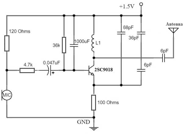
Wireless FM Transmitter Circuit with 2SC9018 Transistor
Working
In the above FM transmitter circuit, the Q1 transistor works as an oscillator & Q2 transistor works as an RF power amplifier. Thus, this simple circuit won’t adjust its frequency by contacting the antenna as an outcome of the Q2 transistor which isolates the antenna using the oscillator. Here, both the L1 & L2 are equal to 10 turns with 1mm enameled wire close warped on a 3mm structure.
Thus, the C4 trimmer capacitor is used to change the frequency whereas the C5 capacitor is used to coordinate the oscillator toward the RF amplifier stage. So here, output adjustment by altering the C5 capacitor is important to obtain a complete yield from the circuit, thus you need to use a field strength meter to adjust the C5 capacitor for the maximum yield.
So antenna will be a 12-inch antenna which will reduce the range of the transmitter. The most severe range with this antenna will be 2 km (or) above the open section. Generally, a wireless FM transmitter is used to play audio gadgets on automobile radios & stationary audio broadcasting on Television and PCs.
Connecting a base resistor to the base terminal of the transistor is mandatory to avoid it being damaged. So, please refer to this link for; Choosing Base Resistance for Transistors in Electronic Circuits.
Advantages & Disadvantages
The advantages of the 2SC9018 transistor include the following.
- It has a high frequency response and its availability is more.
- It has reliable performance.
- These are less cost, so easy to design.
- These transistors don’t need more power to operate.
- They can operate at extremely low voltages because they are made from different materials through a low melting point.
- These are versatile.
The disadvantages of the 2SC9018 transistor include the following.
- These transistors have less thermal stability.
- They generate a lot of noise.
- They have a slow switching time as compared to the higher alternating frequency of voltage & current.
- They have complex control.
Applications
The applications of the 2SC9018 transistor include the following.
- 2SC9018 transistor is designed to be used in amplitude modulation & frequency modulation applications.
- It is used to design electronic projects due to its durability and reliable performance like FM transmitter circuits.
- This transistor is used within RF amplifier circuits because of its high-frequency response to amplify very weak radio signals within devices like; communication receivers, RF signal processing equipment, and FM radios.
- It is very popular in oscillator circuits that produce stable frequency signals.
- This transistor is appropriate to use in LNAs (low noise amplifiers) which improves the S/N ratio within communication systems.
- 2SC9018 is used in mixer circuits in RF applications wherever two frequencies are united to turn out new frequencies.
- This transistor is used in IF amplifiers of superheterodyne receivers, wherever they amplify the IF before it is processed (or) demodulated.
- It is used in class C amplifiers for different applications like; RF power amplifiers within transmitters.
- It is used in different toys and electronic gadgets because of its availability & performance which need efficient and compact RF circuits.
Please refer to this link for the 2SC9018 Transistor Datasheet.
Thus, this is an overview of the 2SC9018 Transistor, pinout, specifications, circuit, working, and applications. So, this is an NPN type silicon transistor that is used to work in RF applications however it can also be utilized as an amplifier or switch for audio & signal amplification purposes. As compared to BJTs, this transistor works with higher frequencies so that it can be utilized in RF applications. Thus, it also used widely by hobbyists and electronic tinkers. Furthermore, it is also utilized in different commercial devices and appliances. Here is a question for you, what is the SS9018 transistor?