Power transistors play a key role in many digital devices that operate at high ranges of voltages because they have large electric potential. These transistors are made with high-performance semiconductor materials like germanium and silicon. The main function of these components is to amplify and regulate a certain range of voltage & handle low-range voltages. Power transistors were developed by William Shockley, John Bardeen, and Walter Brattain in 1947 to amplify and regulate high-range voltages. These transistors handle above 1Amps of collector current and must have less o/p resistance to carry large load currents & very good junction insulation to oppose higher voltages. This article discusses an overview of the BD244 power transistor, pinout, specifications, circuit, and its applications.
What isBD244 Power Transistor?
BD244 is a PNP-type medium power transistor that is available in the TO-220 package. This transistor is manufactured within planar technology including Base Island layout. So it shows excellent high gain performance united with extremely low saturation voltage. This transistor is available in four variations; BD244, BD244C, BD244B, and BD244A where each variation includes a different collector-base, collector-emitter, and collector-emitter-sustaining voltage.
All these variations can be alternatively used in applications that need voltage under -45Volts, however, if your load needs more than that voltage then you must choose the one that suits your necessities. These transistors are designed to be used in amplifier and switching applications.
This transistor’s absolute maximum ratings mainly include; the max collector current (CC) of -6Amp, BD244 transistor’s max collector-emitter voltage of -45V, BD244A transistor have -60V, BD244B transistor have -80 & BD244C have -100V. Similarly, the BD244 transistor’s max collector-base (CB) voltage is -45V, the BD244A variation is -60Volts, the BD244B variation is -80 & BD244C variation is -100V.
While looking for a suitable transistor for your application based on a few factors, it is very important to look into a few points on How to Select a Transistor.
Pin Configuration:
The pin configuration of the BD244 power transistor is shown below. This transistor includes three pins which are discussed below.
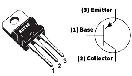
BD244 Transistor Pin Configuration
- Pin-1 (Base): This pin controls transistor biasing by turning it ON and OFF.
- Pin-2 (Collector): This pin allows the current flow.
- Pin-3 (Emitter): This pin drains out the current.
Features & Specifications:
The features and specifications of the BD244 power transistor include the following.
- BD244 is a PNP-type power transistor.
- It is available in the TO-220 package.
- Its maximum collector current or IC is –6Amps.
- The peak collector current maximum is -10Amps.
- The maximum VCE of the BD244 transistor is -45V, the BD244A transistor is -60V, the BD244B transistor is -80 and the BD244C transistor is -100V.
- The Max VCB of the BD244 transistor is -45V, the BD244A transistor is -60V, the BD244B transistor is -80, and the BD244C transistor is -100V.
- The maximum emitter to base voltage or VEBO is 5 volts.
- Maximum collector dissipation or Pc is 65 Watt
- DC gain or hFE minimum is 15 TO 30.
- Maximum operating and storage temperature ranges from -65 to +150 Centigrade.
- Its maximum emitter to base voltage is -5 V.
- Its continuous collector current is -6 Amps.
Equivalent & Complementary Transistors
Equivalent BD244 power transistors are; MJE15031, MJE15029, TIP137, KSA1010, TIP107, BDX54C, BDW94C, BDX34C, BDW74C, BDW24C, BDW48, BD902, BD546C, BD652, 2SB1626 and 2SB886. A complementary BD244 PNP power transistor is a BD243 NPN transistor. The SMD BD244 transistor versions are; 2STF2550 in SOT-89, 2STN2550 in SOT-223 & BDP948 in SOT-223.
Replacing a suitable transistor in any circuit based on requirement is very important. To know how to replace it, please refer to this; Replacing Transistors in Electronic Circuits: Factors and Considerations.
How to use BD244 Power Transistor Safely for a Long Time in a Circuit?
Always use this transistor under 20% of its complete maximum ratings. Thus, based on the above 20% rule, the max collector current is -6Amps but should not drive any load above 4.8Amps. The collector-emitter maximum voltage of the BD244 transistor is -45V however we will not utilize above 36Volts. The max BD244A transistor voltage is 60Volts, however, we will utilize a maximum of 48Volts, The BD244B transistor is 80V however we will only 64Volts & BD244C transistor maximum voltage is -100Volts, but we will use only 80Volts.
Always use a proper heat sink with this transistor. Its pin configuration must be verified before utilizing it within the circuit and always operate and store this transistor at >-65°C and <+150 degrees centigrade temperature.
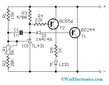
Li-ion Lipo Battery Balance Circuit with BD244 Power Transistor
A simple Li-ion lipo battery balance circuit with a BD244 power transistor is shown below. This circuit is useful in balancing series connected Lion LiPo batteries. In two or three series connected batteries, particularly balanced batteries charging is very significant. If a battery group without a balance circuit fails in a short time.
The required components to make this circuit mainly include; resistors 15K, 20K, 470R, 22K, 1K, 5K, 1N4148 diode, Led3mm/2mA LED, 1n capacitor, BD244C & BC556 transistors and TL431 regulator. Connect this circuit as per the simple diagram shown below.
Voltage Limiter to Charge Li-Ion & Li-Pol Cells
Voltage Limiter to Charge Li-Ion & Li-Pol Cells
Li-Ion & Li-Pol batteries are extremely sensitive to overcharging, so the highest charge can be decided by the charge voltage size. Thus, it will be 4.20V for all conventional cells. The limiter does not permit this voltage to enhance & the extra charge current can be changed into heat. Here, an LED gives a signal whenever the limiting voltage is attained. So the limiter behaves approximately like a perfect Zener diode.
A voltage limiter in the above circuit is very useful in enhancing the quality of charging and also extends the battery’s life. We can also charge the battery pack exclusive of a limiter but its life will be shorter certainly. Additionally, the risk of overcharging is enhanced by increasing the number of series-charged batteries exclusive of a limiter.
Working
A series of cells must have inner connections among the cells. After that, a limiter circuit is simply connected to every cell in parallel. Here, the limiter is connected during charging only, if possible using an auxiliary connector device, it is enough if it is sized for the highest charging current (or) less. So, the wire length must be 30 cm maximum approximately. If the polarity is upturned then the limiter will not be damaged.
Before charging is started, the limiter needs to be connected to the cell group. After that, we start charging. So the limiter does not affect the charging procedure in any way if everything is well. The limiter LED only lights up at the final charging stage, whenever the charging current is small already. If the charger is exciting with a lower voltage than the set on the limiter, then LEDs may not illuminate even at the charging end.
Let’s imagine that a discharged set is being charged, the former limiting diodes will light up from the start of charging, and the variation between the cells will be greater, then signaling some changes within the cell parameters.
Whenever charging at complete current, signaling should never happen within the phase and not right away after charging. In these cases, we stop charging immediately & analyze the cause which is a faulty cell (or) a cell completely with less capacity. For a set of parallel-connected cells, it is essential to separate the parallel cells and discover the faulty cell. Here, the doubtful cell will have a different voltage as compared to the others even whenever it is inactive.
Connecting a base resistor to the base terminal of the transistor is mandatory to avoid it being damaged. Please refer to this link for; Choosing Base Resistance for Transistors in Electronic Circuits.
Limiter Settings
If we have a charger that charges up to 4.15Volts, thus we cannot change it. So is suggested to set the limiter to 4.15Volts (or) to 4.16Volts if possible. Some processor chargers do not calculate the voltage very precisely.
In the processor charger’s case, it is essential to make sure that the charging is ended properly even with the attached limiter. So these chargers’ behavior can be determined by the program & may be different for different types.
The limiter can be set as; the stabilized source can be set to about 6 Volts in the laboratory and the current is limited from 10 to 50 mAmps. If a limiter block is connected to the source, LED lights up and the required voltage can be set with the trimmer.
If we do not contain a laboratory source through current limiting, then a source (or) an accumulator is used with a 12V voltage. The limiter’s one block we set can be connected to a 12V/50mA bulb to the source.
Cooling
In regular operation, whenever individual cells are fine-tuning only in the final charging phase, then the limiting transistor power loss is very small. In the occurrence of a serious fault only, one of the bank cells can have a larger current supply throughout the limiter. Here the provided coolers can give heat dissipation up to 1A current.
If we imagine that faulty cells occur throughout use & utilize a larger charging current, then it is required to use a forced cooling or larger cooler. After that, we mount the transistors on insulating pads above a common cooler. So the maximum well-cooled limiter current is approximately 3 Amps.
Limiter as an Active Voltage Divider
The limiter can be utilized even if we contain a charger for three cells & need to charge one (or) two cells only. We fix the limiter to the output of the charger & connect single or two cells simply to the limiter terminals. Here, the limiter block will not contain any connected cells, and it will decrease the voltage mainly for the remaining cells. So this technique is suitable only for a little current due to an energy drawback – the disconnected cells’ energy can be changed into heat.
The limiter in this case must withstand the highest charging current constantly. It is about 0.70 Amps with the supplied limiter and it is required to utilize a larger cooler (or) forced cooling through a fan mainly for a larger current. But, this technique is very suitable for measuring as well as shaping objects. So, one three-cell charger & one limiter will be enough in most cases.
Advantages & Disadvantages
The advantages of BD244 power transistors include the following.
- These transistors have high voltage gain, high current density, and low forward voltage.
- This transistor has a large bandwidth gain.
- It is very simple to turn ON & OFF.
- These transistors operate at switching frequencies from 10 to 15 kHz.
- They can block extremely high voltage whenever they are switched off.
- These can be utilized to control delivered power to loads, choppers, and inverters.
The disadvantages of BD244 power transistors include the following.
- It has less thermal stability.
- These are hard to control.
- These transistors can be highly noisy.
- They have a lower reverse blocking capacity.
- They can’t operate adequately above a 15 kHz switching frequency.
Applications
The applications of the BD244 power transistor include the following.
- The BD244 PNP power transistor is used in general-purpose amplifier & switching-based applications.
- This transistor can be used within the driver & output stages of hi-fi-based amplifiers.
- These transistors are used in series & shunt regulators.
- It is used in linear and switching applications.
- These are used in battery chargers; high power-based audio amplifier circuits, BMS applications, motor drivers, and switching or driving loads <6Amps.
Please refer to this link for the BD244 Power Transistor Datasheet.
Thus, this is an overview of the BD244 power transistor, pinout, features, specifications, circuit, working, pros, cons, and applications. This is a PNP-type silicon power transistor, available in a TO-220 package. This transistor is mainly designed for use within medium power switching and linear applications. Here is a question for you, what is a BD243 transistor?