PWM controller ICs are simple and fixed-frequency control chips that can control nearly any power topology, like boost, flyback, push-pull, buck, forward, etc. Thus, the PWM controller ICs also incorporate a complete set of protections for improved robustness and consistency, even in an extensive temperature range for outdoor applications. Thus the result will be a reduction in the number of outside components, reducing converter cost and size. This article explores its TL494 IC design like pin out, features, internal structure & its applications.
What is the TL494 IC?
The TL494 is a PWM (pulse-width modulation) control IC, available in 16-pin TSSOP, PDIP, SOP, and SOIC packages. It is designed to be used within different power supply circuits. This IC provides many features like error amplifiers, output control circuits, and adjustable oscillators. The TL494 PWM controller IC is mainly designed to produce & control pulse width modulation signals, which are necessary for very efficient power conversion & regulation.
This IC includes numerous elements that ensure smooth power management. In addition, it can also have two error amplifiers, which help in correcting voltage fluctuations, and also a tunable oscillator that easily adjusts the PWM signal’s frequency. The built-in circuits of this IC manage timing & control the output by allowing the TL494 IC to adjust power supply circuits depending on specific performance requirements.
The TL494 flexible PWM controller IC is used in industrial, consumer, and automotive electronics. This IC is commonly used in SMPS & other power electronics applications, wherever exact PWM signal control is required. The TL494 IC operates in both push-pull and single-ended configurations by ensuring constant and reliable power delivery. Additionally, this IC have a voltage regulator that maintains a consistent 5V reference with 5% accuracy for stable performance.
Pin Configuration:
The TL494 IC pin configuration is shown below. This IC includes 16 pins, which are explained below.
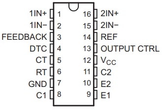
TL494 IC Pin Configuration
- Pin-1 (1IN+): It is a non-inverting input pin of the first error amplifier in the IC.
- Pin-2 (1IN-): It is an inverting input pin of the first error amplifier in the IC.
- Pin-3 (Feedback): It is an input pin used for feedback.
- Pin-4 (DTC): It is an input of a dead-time control comparator.
- Pin-5 (CT): It is a capacitor terminal utilized to set the frequency of the oscillator.
- Pin-6 (RT): It is a resistor terminal utilized to set the frequency of the oscillator in the IC.
- Pin-7 (GND): It is a ground pin of the IC.
- Pin-8 (C1): It is the collector terminal of transistor o/p-1 in the IC.
- Pin-9 (E1): It is the emitter terminal of transistor o/pt 1 of the IC.
- Pin-10 (E2): It is the emitter terminal of transistor output-2
- Pin-11 (C2): It is the collector terminal of BJT o/p-2 of the IC.
- Pin-12 (VCC): It is a positive supply of the IC.
- Pin-13 (Output CTRL): It chooses s single-ended or parallel output (or) push-pull operation of the IC.
- Pin-14 (REF): It is the 5V reference regulator output pin of the IC.
- Pin-15 (2IN-): It is the inverting input of the second error amplifier in the IC.
- Pin-16 (2IN+): It is the non-inverting input of the second error amplifier in the IC.
Features & Specifications:
The features and specifications of the TL494 IC include the following.
- The TL494 IC provides complete features to handle PWM.
- This IC is available with an oscillator and works in both master & slave modes.
- It has amplifiers to provide feedback & control.
- This IC has a 5V reference internally to maintain stable operation.
- This IC permits you to regulate the dead time to prevent switching overlap.
- Its output transistors handle up to 500mA, thus it provides flexibility for a variety of uses.
- This IC is set for either single-ended or push-pull operation.
- It prevents the chip from functioning if the voltage is too low for secure use.
- This IC is available in different versions for special uses and cars.
- It provides lead-free packaging mainly for secure & environmentally friendly use.
- Its operating voltage ranges from 7V to 40V.
- This IC has two outputs.
- The switching frequency is 300 kHz.
- Its maximum duty cycle is 45%.
- The output voltage is 40V.
- Its output current is 200 mA.
- The max o/p current for two PWMs is 250 mA.
- The fall time is 40 ns, and the rise time is 100 ns.
- Temperature ranges from -65°C to 150°C.
Equivalents & Alternatives
Equivalents to the TL494 IC include TL3842, and UC3843. Alternative TL494 ICs are UC2842 and SG2524.
TL494 IC Structure
The TL494 IC internal structure is shown below. This IC includes different components like PWM control, oscillator, error amplifiers, dead time control, and output control, which are explained below.
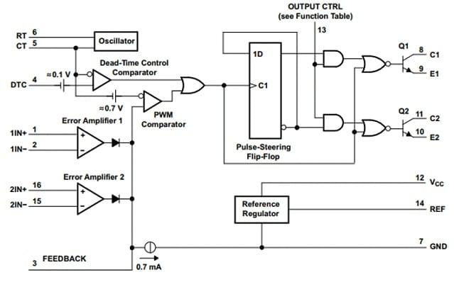
TL494 IC Structure
PWM Control
The TL494 IC is a PWM controller chip that produces a set of pulses through a duty cycle or variable width, thus, it controls the delivered power to a load.
Internal Oscillator
This IC has an internal oscillator that produces a saw tooth signal thus, it is the foundation mainly for the pulse width modulation signal.
Error Amplifiers
This IC includes two error amplifiers that compare the o/p voltage to a reference voltage, thus it allows for feedback control & output voltage regulation.
Dead-Time Control:
The TL494 IC has a DTC or dead-time control comparator that initiates a short period between the two output transistors, switching within a push-pull configuration by avoiding a shoot-through current.
Output Control
The IC has an output control circuit that is configured for single-ended or push-pull output operation based on the application.
Output Transistors
The output transistor of this IC includes an uncommitted emitter & a collector terminal. So, these two terminals accept or provide up to 200 mA of current. Whenever the transistor’s saturation point is set in the CE mode, it turns below 1.3 volts. In addition, it is also < 2.5 Volts whenever arranged in a CC manner.
How does the TL494 IC Work?
The TL494 fixed-frequency PWM IC works by controlling the switch-mode power supply. So this IC includes different components such as an oscillator, a dead-time control comparator, error amplifiers & output control circuits, and it is used to provide a stable current by changing the output voltage toward the load.
It is a fixed frequency & dual PWM variable duty cycle control circuit. This IC does not need any external electronic components to work, except for some capacitors and resistors for an oscillator. Thus,this oscillator is accountable for producing a sawtooth signal based on the ‘CT’ timing capacitor. This IC produces signals by contrasting a saw-tooth waveform, including two error amplifiers’ control signals. Thus, the output signal will be turned on whenever the sawtooth voltage is greater than the voltage at the outputs of the error amplifiers.
If the sawtooth voltage is below the control signal voltage, then the output signal will be low. If the sawtooth voltage is superior to the control signal voltage, then the output signal will be high. Thus, the pulse-steering FF (Flip-Flop) in the IC transmits the PWM o/p signal to the output transistors.
TL494 IC PWM Control Circuit
The TL494 PWM controller IC controls the power supply by turning ON and OFF signals very fast. Thus, this procedure allows it to manage how much power is supplied to a device. This feature adjusts how long the signal will stay on while maintaining the frequency or speed of the signals the same, known as a duty cycle.
It doesn’t need more external components except resistors & capacitors. In addition, in the controller IC, there is an oscillator that makes a special wave model known as a sawtooth waveform. This waveform is compared with other signals using error detectors in the controller IC.
If this wave is higher than the error signal, then the controller sends a signal to turn on the power. If this signal is lower, it turns off the power. After that as to perform, the PWM controller controls how much power is sent to various parts of the circuit by making it very efficient.
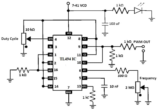
TL494 IC PWM Control Circuit
Oscillator Frequency
The oscillator frequency in the TL494 IC affects how the sawtooth waveform shape is created. Thus, this waveform controls how the pulse-width modulation (PWM) outputs perform, it will affect the overall circuit performance.
The frequency can be set by choosing the correct values of two parts: the RT (timing resistor) and the CT (timing capacitor). To select these parts, the frequency can be controlled to match what you require by using the following formula.
Frequency = 1/(RT x CT)
Here, you can control how quickly the PWM controller turns on and off by modifying the RT & CT values.
Advantages & Disadvantages
The advantages of the TL494 IC include the following.
- It is a cost-effective and versatile IC.
- These ICs incorporate all the required PWM control functions like an adjustable oscillator, error amplifiers, output control circuits, dead-time control, design simplifying, and component count reduction.
- The uncommitted o/p transistors permit either emitter-follower or common-emitter configurations by providing flexibility within the external circuitry driving.
- This IC provides the choice of push-pull or single-ended output operation.
- Its internal 5V, 5%-precision regulator offers a stable reference voltage, thus it simplifies design & decreases the requirement of external components.
- The dead-time control comparator of this IC gives a fixed offset that allows control above the whole range and avoids double pulsing.
- The internal circuitry of this IC avoids the opportunity of any output being pulsed twice throughout the push-pull operation by ensuring consistent operation.
The disadvantages of the TL494 IC include the following.
- Its integrated circuit can be broken through ESD.
- It generates EMI or electromagnetic interference.
- This IC causes noise or interference to other devices.
- This IC has heat dissipation and increased switching losses.
Applications:
The applications of the TL494 IC include the following.
- The TL494 IC is commonly used in inverters, switching power supplies, and other applications where accurate power delivery control is required.
- This IC is used mainly for handling power distribution within electronic devices through a pulse-width modulation technique.
- This is an ideal IC for DC-to-DC and buck and boost converter topologies, thus it allows efficient and reliable power change.
- Additionally, these are used in different switching power systems, so they include half-bridge, full-bridge, & single-ended advanced dual-tube-based configurations.
- It is used within isolated, non-isolated, and AC-to-DC power supplies with PFC (Power Factor Correction).
- It is utilized in server power supplies, telecom, or server AC to DC supplies, and dual controller analog-based applications for server AC/DC & telecom supplies.
- These are used in solar power and micro-inverters.
- It is utilized to control the flow & conversion of power.
- In addition, these are used in the power supplies of desktops and PCs.
- It is used in the power supply control circuits of the microwave ovens & smoke detectors.
- These are used within both high-end & low-end washing machines.
- It is used within the power control systems of electric bikes.
Please refer to this link for the TL494 IC Datasheet.
The TL494 is a versatile PWM IC in brief, which is designed mainly for power supply applications. Additionally, it provides different features like a 5V regulator, an adjustable oscillator, dual error amplifiers, and dead-time control on a single chip. Thus, the main function of this IC is to simplify the power supply design & implementation by incorporating key functions. Here is a question for you: What is PWM?