PWM controller is a fixed frequency control and very simple integrated circuit, used for controlling nearly any power topology like boost, flyback converter, buck, forward, push-pull, etc. There are many manufacturers which provide high-performing PWM controllers like general-purpose & application-specific. These controllers provide flexibility for covering a wide range of power-supply designs which are utilized within AC-to-DC and DC-to-DC power-conversion circuits for different equipment. This article discusses an overview of the UC3842 PWM controller IC, pin configuration, specifications, and applications.
What is UC3842 PWM Controller?
The UC3842 IC is a PWM controller with fixed frequency current-mode which means it can be utilized for providing a stable current by simply changing the o/p voltage toward the load. This PWM controller is particularly designed to use in DC to DC converters & Off-Line applications.
This IC has a trimmed oscillator, an error amplifier with high gain, a temperature-compensated reference, a current sensing comparator & a high current totem pole o/p to drive a Power MOSFET. The UC3842 PWM controller is used for changing or limiting current within different applications like DC-DC Converters, SMPS, Line voltage regulators, RPS, etc. This IC is suitable to generate PWM signals to control a power switch depending on the current supplied throughout the circuit.
This IC operates in two modes like peak current (or) voltage control. So, the controller within peak current mode changes the peak current of the converter & duty cycle through external feedback circuitry & error amplifier whereas the controller in the voltage control mode changes the duty cycle of the power converter.
Pin Configuration:
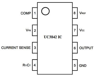
The pin configuration of the UC3842 PWM controller is shown below. This IC includes 8 pins and each pin and its functionality are discussed below.

UC3842 Pin Configuration
Pin1 (COMP/Comparator)): This comparator o/p pin provides a 1MHz low impedance signal depending on the main dissimilarity between the set & current voltage. Generally, it is connected to the ICs voltage feedback pin through a resistor & capacitor.
Pin2 (VFB/Voltage Feedback)): It is an i/p to the error amplifier within the chip. The dissimilarity within the level of voltage can be supplied toward this pin
Pin3 (Current Sense): A shunt resistor is utilized for monitoring the flow of current throughout the circuit & the voltage across it can be provided feedback toward the current sense pin.
Pin4 (Timing Resistor (RT)/ Timing Capacitor (CT)): This IC includes an internal oscillator that sets with an external resistor & capacitor which are connected to this pin.
Pin5 (Ground): It is a GND pin, connected to the ground terminal of the circuit.
Pin6 (Output): This output pin provides the PWM signal depending on the given feedback & we can utilize this to control the power electronic device.
Pin7 (Vcc): It is a voltage supply pin of the IC.
Pin8 (VREF): It is a Reference voltage depending on which the pulse width modulation signal is generated.
Features & Specifications:
The features and specifications of the UC3842 PWM controller are discussed below.
- It includes 8 pins.
- It is a current-mode PWM controller.
- Its operating voltage ranges from 12Volts to 28Volts.
- Its o/p pin current is 200 mAmps.
- Its switching frequency is 500 kHz.
- Its maximum duty cycle is 100 %.
- Its operating current supply is 25 mA.
- It is optimized for DC to DC and offline converters.
- The type of mounting is Through a Hole.
- Its function is step-up, step-down, step-up/step-down.
- Topology is Buck, Boost, Flyback, Buck-Boost & Forward.
- Its frequency is 450kHz.
- Its rise time is 50ns.
- Its maximum duty cycle is 97%
- RoHS Status is ROHS3 Compliant
- The package or case is 8-DIP.
- Its operating temperature ranges from 0°C to 70°C.
- The technology used is BICMOS
- The number of o/p is 1.
- The type of output is the transistor driver.
- Its output current is 1A.
- Its control technique is PWM.
- Its typical fall time is 50 ns.
- Its length is 9.81mm.
- Its width is 6.35mm.
- Its thickness is 3.9mm.
- Its height is 5.08mm.
Equivalent & Alternatives
The equivalent UC3842 PWM controller is UC3843and alternative PWM controllers are; UC3844, UC2842, SG2524, etc.
LED Driver with UC3842 PWM Controller
The LED driver circuit is used for controlling the output voltage of LED strings which are connected in different connections like series, matrix, parallel & independent strings. These LED strings have different kinds of drivers. For LED drivers, output voltage mainly depends on the kind of LED strings & number of LEDs utilized for the LED driver. These LED drivers are generally having a constant current source because LEDs brightness mainly depends on constant current.
At present, most of the lamps used outside include LEDs which are commonly connected in different configurations. Here we are discussing only LED driver design in a series configuration. The LEDs in series configuration are, the first LED’s cathode terminal is connected to the next LED’s anode terminal, and the second LED’s cathode terminal is connected to the third LED’s anode terminal.
The output voltage of the LED driver is measured by simply multiplying LED’s forward voltage drop with a whole number of connected LEDs within the string. For instance, if you are connecting four LEDs in series & every LED’s forward voltage drop is 3 volts then the LED driver’s output voltage must be 4 x 3 = 12 volts.
When all LEDs are connected in series then the same current will be supplied throughout every LED. For series configuration, a LED driver with a constant current source is used. The main drawback of the series configuration of LED is that if a single LED in the string is damaged because of any fault then the string will turn into an open circuit. So there is no flow of current throughout the string then the LEDs will turn off.
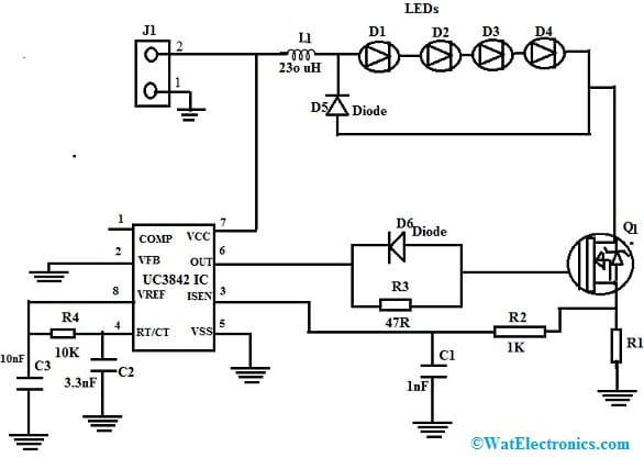
The series LEDs configuration using LED driver with UC3842 current mode controller IC circuit is shown below. In the following circuit, four LEDs in a series connection have 3 volts of forward voltage drop. Thus the output voltage of the LED driver must be equivalent to 12 volts. Here four LEDs are simply connected in series where every LED has 3 volts a forward voltage drop. Thus LED driver output voltage can be calculated as;
LED driver output voltage = No. of LEDs x each LED’s forward voltage drop.
The required output voltage is = 4x 3 = 12 volts.
In the following circuit, the i/p voltage to the LED driver ranges between 10 to 25 volts & we require regulated LED driver output as 12 volts for 3 LED strings in a series configuration. The LED driver in the Series configuration circuit diagram is shown below:
The below circuit is used to power 1.5Amps series LEDs. The main components of this LED driver circuit mainly include UC3842 IC, IRLZ34NS MOSFET, R1 current limiting resistor & inductor design.

LED Driver with UC3842 PWM Controller
Working
The circuit includes four labels which are discussed below. In the first label, at the input side of the LED driver, the input voltage ranges from 10V to 25 volts. Here, the output voltage we required for the LED driver is 12 volts. Thus the voltage needs to be stepped down. A buck converter is used to step down DC voltage. It is a one-kind DC-to-DC converter mainly used to step down DC voltage. The buck converter is designed with the combination of a MOSFET, diode, & inductor which is used in power electronics circuits.
The second label shows the string of 3 LEDs that are connected in the configuration of a series.
In the third label, the current limiting resistor is used to set the current limit for the LED driver circuit. Here current limiting resistor value is known when the current value is known. For instance, an LED driver powers LEDs up to 1.5A. The current limiting resistor is used as a current-sensing shunt resistor. The shunt resistor ‘R1’ is connected through the current sensing pin of UC3842 because this IC is a current mode PWM controller. So it is used for controlling current up to 1.5A. Here for this pin, the reference voltage is set as 1V. So now we have both voltage & current values as I = 1.5 A & V = 1V.
According to Ohm law, the current limiting resistor value can be calculated as;
V = I x R
R = Voltage/Current => 1 / 1.5 = 0.67 ohms
In label-4, UC3842 IC is utilized as a current mode PWM controller. Once the flow of current increase (or) decrease from 1.5A, it regulates the ON/OFF time of Q1 MOSFET by simply adjusting the PWM duty cycle. In the above circuit, the inductor must be made with a ferrite core & choose the correct wire to build the inductor based on the rating of current for the LED driver.
Applications
The applications of the UC3842 PWM Controller are discussed below.
- The UC3842 PWM controller is used to limit/change current within Line voltage regulators, RPS, SMPS, DC-DC Converters, etc.
- This IC is used to supply stable current by changing the o/p voltage to the electric load.
- This IC is designed for DC to DC converter & Off-Line applications.
- It is most frequently used within SMPS circuits.
- SMPS (Switch Mode Power Supplies) circuits, Electronics power supply, Load machines, battery drain circuits, etc.
- This IC is used to design isolated & non-isolated power supplies.
- This IC is used in any application or project where a wide temperature range is necessary.
- It is perfectly suitable in offline converter-based applications because of low startup current & large hysteresis.
Please refer to this link for UC3842 PWM Controller Datasheet.
Thus, this is an overview of the UC3842 PWM controller, pin configuration, specifications, and its applications. Here is a question for you, what is UC384?