In this digitized world, most of mankind’s life turns around sensors and sensors hold a prominent role in our lives. Making every activity as automatic, one can find multiple kinds of sensors in their workstation, home, car and in many other places. So, let’s start with the definition of what sensor means to and how it created a great impact on the lives of mankind ? Sensors are the devices where those receive input signals and provides an output in correspondence with the physical change. The input signals might be heat, pressure, light, motion, vibrations, etc. Current day sensors can easily communicate with electronic devices and used for calculating and many other purposes. Various enhancements in technology allow the development of various kinds of sensors having comprehensive features, augmented fidelity, and enhanced reliability. And the most prominent one of all the available sensors is the Piezoelectric sensor.
Piezoelectric Sensor Definition
Piezoelectric sensors are also termed as piezoelectric transducers are the devices which utilize the piezoelectric effect to exploit few measurable modifications in the forms of temperature, pressure, force, acceleration or strain by converting to the electrical charge. The capability of the piezoelectric material to transform the applied mechanical pressure into electrical change is termed as a piezoelectric effect. The generated electrical charge is directly proportional to the applied pressure.
Piezoelectric Sensor Working
When certain pressure or acceleration is applied to the piezoelectric material, the corresponding amount of electrical charge starts to generate across all the edges of the crystal. The generated voltage can be measured in proportion to the applied pressure or acceleration. Piezoelectric sensors also work on the mechanism of the inverse piezoelectric effect. Here, the principle of operation is, applying certain voltage on the piezoelectric material will trigger the material to alter its shape.
The applied static force outcomes in the subsequent electrical charge across the sensor. On the other hand, this charge will leak away over time because of flawed actions like imperfect insulation, attached electronics, internal sensor resistance, and others.
Accordingly, piezoelectric sensors generally do not suit to measure static pressure. The generated output signal tends to zero also in the availability of constant pressure. The devices are receptive to the dynamic alterations in pressure across the extended scope of pressures and frequencies. So, this dynamic receptiveness corresponds that the devices perform well even to measure minimal modifications in pressure even in the circumstance of a high range of pressure environments.
While in accelerometers, a certain amount of seismic pressure is applied to the crystal to pass the applied pressure to the piezoelectric devices. When movement is initiated, seismic pressure starts to load the piezoelectric material as per Newton’s second law of motion. Then the device discharges the charge that is utilized for the calibration of movement.
Specifications
The specifications of this sensor include the following.
Sensitivity – It is measured in the proportion of relative output signal to the resultant change.
Reliability – This corresponds to the ability of the sensor to maintain certain features in limit under working circumstances.
- Works under the impedance value of ≤500Ω
- Operates in the voltage range of ≤30Vp-p
- Operating temperature 20°C~+60°C
- Generally stored under the temperatures of 30°C~+70°C
- Low Soldering temperature Minimal
- Strain sensitivity 5V/µƐ
- Mostly used material Quartz (Due to enhanced flexibility)
Basic Circuit
The below diagram explains the operation of the piezoelectric sensor and shows the result of it.
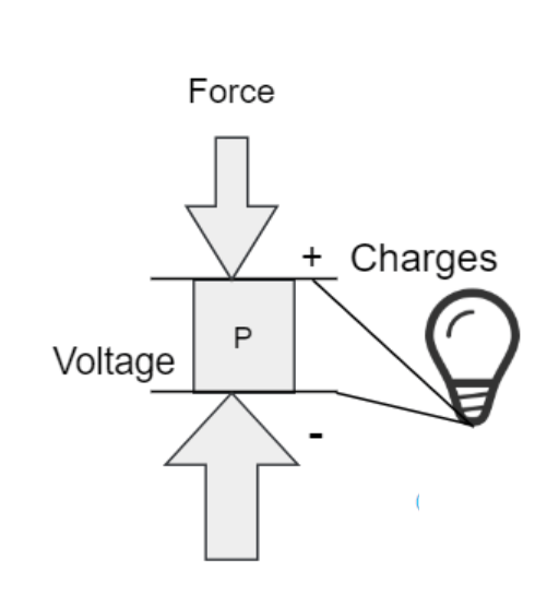
basic circuit result
Piezoelectric Sensor Circuit using Arduino
As there are numerous applications on how to implement a piezoelectric sensor using Arduino, here we go with the application of how to use a piezo element to identify vibration in the element (might be door knock or table knock).
Required Hardware Components
- Arduino Board
- Piezoelectric plate
- 1M Ω resistor
- Solid surface
Working
As we have already discussed that piezoelectric devices generate output voltage when it is provided with a motion of vibration or mechanical pressure. In the same way, when the corresponding amount of voltage is applied across the piezo element, it results in motion and produces a tone.
The sketch read out the piezo result through the analogRead () command, thus converting 0 to 5 volts voltage range to the numerical range of 0 to 1023 in the procedure that is stated as an analog to digital conversion or ADC. When the delivered output range is greater than that of a specified threshold limit, then the board delivers the tone “Knock” across the serial port.
Initially, piezoelectric elements are polarized which means that voltage is passed through them in a particular direction. In general, make the connections as follow
• Black wire – Connected to the minimal voltage (Ground)
• Red wire – Connected to the maximum voltage pin (Analog pin 0)
• 1M Ω resistor – Connected in parallel to the piezo element (Limits both I (current) and V (voltage) generated by the piezo and to handle the analog input).
Schematic Diagram
The below image specifies the detailed pin connection of the piezoelectric sensor using Arduino including with input and output pins along with power supply.
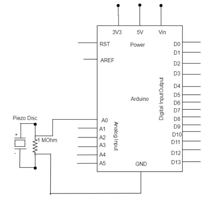
schematic diagram
Code
The below code defines that the incoming piezo information is measured relative to the threshold value specified by the user. One can either maximize or minimize this limit, to boost up the sensor’s whole sensitivity value.
const int ledPin = 13; // LED is connected to pin D13
const int knock sensorknockSensor = 40; //piezo element is connected to Analog input A0 (pin 40)
const int threshold = 100; //specified threshold limit when the detected sound is either knock or not
//altering variables
int sensorReading = 0; // declaration of a variable to store the value sent from sensor pin
int ledState = LOW; // declaration of a variable to store the status of LED, to toggle the light
void setup (){
pinMode (ledPin, OUTPUT); // declaring ledPin as the output pin
Serial.begin (9600); // using of serial port
}
void loop (){}
sensorReading = analogRead (knockSensor);
if (sensorReading >= threshold)}
ledState = !ledState; // toggle the state of the ledPin
digitalWrite (ledPin, ledState); //automatically update the status of LED pin
serial.println(“Knock”); // sends back the Knock string to the computer
}
delay(100); // declared to avoid any kind of overloading of the serial port buffer
}
Piezoelectric Sensor Applications
These Days, the additional enhancement of humanmade piezo objects — consisting of piezoelectric ceramics — the implementation of piezoelectricity in electronic appliances is increasing at an exciting speed.
A few of the applications are as below.
- Piezoelectric sensors in industrial applications as engine knock sensors
- Piezoelectric actuators in industrial applications as diesel fuel injectors
- Piezoelectric sensors in medical applications as ultrasound imaging
- Piezoelectric actuators in consumer electronics as piezoelectric printers
- Music applications
- Défense applications and many more
So, there are a vast number of applications using piezoelectric sensor devices right from its developmental phase. Here is a question for you, what are the benefits of a piezoelectric sensor?