An adjustable voltage regulator is a type of voltage regulator IC whose regulated o/p voltage can be changed over a range. So there are two variations of the same like positive adjustable voltage regulator & negative adjustable regulator. The positive adjustable voltage regulator example is LM317. Similarly, the negative adjustable voltage regulator example is LM337, the complement of LM317 IC. An adjustable voltage regulator IC generates a DC output voltage. It can be changed to any other certain voltage range value. So, this regulator is also known as a variable voltage regulator. This regulator’s DC output voltage value can be either negative or positive. This article elaborates on one of the adjustable voltage regulators like LM723 IC.
What is LM723 IC?
The LM723 IC is a monolithic incorporated programmable voltage regulator, available in a 14-lead DIP package. This IC is mainly designed to be used in series regulator applications to generate up to 150 mA output current on its own, however, additional transistors can be attached to deliver any required load current.
This is an adjustable voltage regulator IC used for the current regulator, temperature controller & shunt regulator. So it can provide a maximum output voltage range and up to 10A current by connecting a series pass transistor with it. This IC has a wide operating temperature range thus it can endure for a long time. In addition, this IC can be used as either a switching or linear-type voltage regulator but it is designed especially for series regulators.
The LM723 is a switchable voltage regulator IC that works with a 150-output current in series without the need for an outside pass transistor. Whenever we use an external transistor, the load can be driven with 10 amps of current. So the output voltage can be changed from 3 volts to 40 volts whereas the input voltage source has 40 volts maximum. This regulator IC can be used as a shunt regulator, temperature controller, and current regulator in a wide range of applications.
How LM723 IC Work?
The LM723 voltage regulator IC works as an adjustable voltage regulator, thus it can supply a constant output voltage in a wide range with an internal circuitry to evaluate the output voltage to a reference voltage. The desired output voltage can be adjusted with the current flow throughout an exterior pass transistor to keep voltage whenever the input voltage (or) load changes.
The input voltage is provided to the suitable pin on the LM723 IC. After that, an external voltage divider network can be connected to the “adjust” pin of the IC to set the preferred output voltage. So the internal circuitry contrasts the voltage at the “adjust” pin to the actual o/p voltage. If there is a variation between the desired & actual output voltage, then the error amplifier can produce an error signal. This signal controls the flow of current throughout the external pass transistor by adjusting the output voltage to equal the preferred level.
LM723 IC Pin Configuration:
The LM723 IC pin configuration is shown below. So this IC includes 14 pins which are explained below.
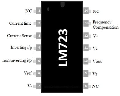
LM723 IC Pin Configuration
- Pins -1,8 & 14 (NC): These are not connected pins of the voltage regulator IC.
- Pin-2 (Current Limit): This pin limits the current throughout the IC. This pin is connected to a low-value resistor arranged between the load & ground to set the highest load current.
- Pin-3 (Current Sense): This pin limits the current and is used in fold-back applications. This pin functions in combination with the CL pin for current limiting.
- Pin-4 (Inverting Input): This pin supplies constant o/p voltage. So this pin is connected simply to the voltage divider from the output voltage.
- Pin-5 (Non-inverting Input): This pin supplies a reference voltage to the inside op-amp of the IC. This pin is connected normally to the internal reference voltage.
- Pin-6 (Vref): This pin provides a nearly 7v stable reference voltage for feedback & control. So it can be externally used within the circuit.
- Pin-7 (-Vcc): It is a GND pin of the IC that functions as the reference point mainly for all voltage levels in the IC.
- Pin-9 (Vz): This pin helps in designing negative regulators. So this pin is connected simply to an internal zener diode to produce the reference voltage.
- Pin-10 (Vout): This pin provides the output voltage of the IC.
- Pin-11 (Vc): This is the collector input of the series pass transistor which is directly connected to the positive voltage supply if an external transistor is not utilized.
- Pin-12 (V+): This is the positive supply input pin of the IC.
- Pin-13 (Frequency Compensation): A capacitor from this pin is connected to GND to soothe the action of the internal error amplifier. So this pin is used for Stabilization & frequency compensation.
Features & Specifications
The features and specifications of LM723 IC include the following.
- LM723 is an adjustable voltage regulator IC.
- This IC is available in 14-pin DIP & SO-14 micro packages.
- Its unnecessary output current is 150mA without utilizing an exterior pass transistor.
- It has a 40V maximum input voltage supply.
- This IC provides a modifiable output that ranges from 3V to 37V.
- It is used to design linear and switching regulators.
- This IC is used for different operations like series, positive, floating, shunt & negative.
- The reference voltage is 7 volts always.
- Its ripple rejection is 74 dB.
- The current supply of Vz pin will be 25mA,
- The Vref pin current supply is 15mA
- Its line & load regulation will be 0.01%Vout and 0.03% Vout.
- The operating temperature range is from -55°C to +150°C.
Functional Block Diagram
The LM723 IC functional block diagram is shown below which is divided into four main blocks like Temperature compensated voltage reference source or zener diode, op-amp circuit as an error amplifier, series pass transistor, and transistor to restrict output current which are explained below.
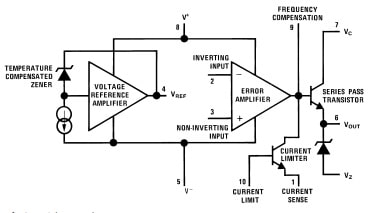
Functional Block Diagram
Zener Diode
The temperature-compensated voltage reference source (Zener diode), constant current source & reference amplifier comprise the reference element. The constant current source makes the zener diode work at a fixed point to obtain a fixed voltage supply using the zener diode. Here the output voltage can be compared using zener diode potential. For this ‘Vref’ is connected directly to the error amplifier’s non-inverting input terminal.
Error Amplifier
Here error amplifier is known as a high-gain differential amplifier. So its inverting input terminal can be connected to the entire regulated output voltage or a fraction of that from the outer surface. A potential divider with two scaling resistors can be used for later cases. So scaling resistors help in obtaining multiplied reference voltage (or) scaled-up reference voltage.
Series Pass Transistor
Error amplifier in this functional diagram controls the Q1 series pass transistor that works like a variable resistor. This is a small power transistor with 800 watts of power dissipation. An unregulated power supply source can be connected to the collector terminal of the series pass transistor. Here, the Q2 transistor works like a current limiter in a short circuit state.
The frequency response of the error amplifier can be controlled by the frequency compensation terminal, so by connecting a 100 pF small capacitor between frequency compensation & inverting input terminals, the necessary roll-off can be obtained.
In the internal structure of the IC, both the inverting and non-inverting terminals of the error amplifier are obtainable on the external pins of the LM723 IC. So this IC becomes flexible and versatile to use. The only limitation of this is internal reference voltage is 7V, thus we have to utilize two different circuits to obtain regulated outputs of < 7V and >7 volts.
Equivalent & Alternatives:
Equivalent LM723 ICs are; MC1723CP, LM723N, LM723CN, LM723QML, UA723MJ, LM723CMX, JL723BIA, UA723MJ/883B, M38510/10201BCX, etc. Alternatives to LM723 ICs are; LM317 IC, LM338 IC, µA723, AMS1117 IC, etc.
How to use LM723 IC Safely in a Circuit for a Long Time?
To get long-term performance by using an LM723 IC in a circuit, it is recommended to use proper heat sinking to protect from overheating. External pass transistors must be used for high current-based applications. Choose the voltage divider resistors cautiously to set the preferred output voltage. Use the current limit pin to guard against extreme load currents and need to ensure your circuit design always before providing a power supply to keep away from potential harm.
Key Points:
The following key points must be remembered while using LM723 IC in any application.
- Always utilize an external NPN transistor like a pass element in high current applications to enhance the current handling ability beyond the internal limitations of LM723 IC.
- Choose the resistor values in the voltage divider to set the preferred output voltage, because this decides the voltage regulation point.
- Use the pin 2 or current limit pin to defend the circuit from too many load currents by simply connecting an appropriate resistor.
- A heat sink must be used if the circuit draws significant current to dissipate generated heat by the IC, particularly when utilizing an external pass transistor.
- Always make sure the input voltage that must be greater than the preferred output voltage.
- Place capacitors correctly at the input & output of the UC to develop stability and decrease noise.
- The pin-out and each pin functionality must be known properly in your circuit.
- Set the preferred output voltage in a wide range with external resistors.
- This IC can be configured to work as a linear regulator for low-power applications (or) a switching regulator mainly for higher efficiency.
- An external pass transistor must be added to achieve higher output currents significantly.
Voltage Regulator Circuit using LM723 IC
The voltage regulator circuit with LM723 IC is shown below. By providing a 9V input power supply to the circuit, the regulated supply can be adjusted from 4 volts to 8 volts with the potentiometer. So this regulator IC provides up to 10A excessive current by connecting an external pass transistor with correct circuitry. The maximum voltage supply of this IC is 40v and the output voltage ranges from 3volts to 37volts with 150mAmps output current without utilizing an external pass transistor.
The required components to make this voltage regulator circuit mainly include; LM723 IC, 10k resistor, 100pf, 0.1uf capacitor, 10k potentiometer, 9V battery, and connecting wires. Connect this circuit as per the diagram shown below.
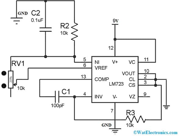
Voltage Regulator Circuit using LM723 IC
Working
The LM723 IC is designed for series regulator application with 150mA output current without an external pass transistor. If an external pass transistor is used then it provides up to 10 Amps of current supply to drive any load. The maximum input supply is 40v and its output voltage mainly ranges from 3volts to 40volts. This voltage regulator IC has a low standby current drain. So it allows us to utilize the regulator IC as linear (or) fold-back current limiting with -55 °C to 150 °C operating temperature.
This voltage regulator circuit works as; when a 9volts supply is given to the reference amplifier through PIN-12 (V+ pin) of LM723 IC to obtain a stable output voltage at Pin-6 (Vref pin). After that reference voltage is transmitted to the Pin-5 or non-inverting pin of the regulator IC through a potentiometer & capacitor. The voltage supply at the non-inverting pin can be utilized to compare through inverting pin voltage.
If the voltage supply at the non-inverting terminal is greater than the inverting pin, the series pass transistor will get forward-biased. So, it allows the current supply throughout the CE, and we can get the output voltage throughout pin-10. In this voltage regulator circuit, an RV1 potentiometer is used in place of an R1 resistor to regulate the voltage according to the necessity.
Advantages & Disadvantages
The advantages of LM723 IC include the following.
- The output voltage can be set based on the circuit necessities.
- It allows high current output by using external transistors to handle bigger loads.
- It generates minimum noise within the regulated output voltage.
- These are inexpensive due to mass production.
- It can be adapted easily to different circuit requirements by regulating external components.
- It is used & considered widely as a reliable voltage regulator.
The disadvantages of LM723 IC include the following.
- The current limiting feature of this IC uses a transistor, switched on by a voltage drop of the current sensing resistor. So this can lead to voltage headroom & wasted power.
- This IC’s current limiting feature is sensitive to overload.
- It has partial built-in ESD (electrostatic discharge) protection.
- This IC has a reasonable error amplifier gain.
- The “knee” current includes 2mV/°C of a temperature coefficient.
Applications
The applications of LM723 IC include the following.
- The LM723 IC is used to make adjustable power supplies and battery chargers.
- This IC is used as a voltage regulator, shunt regulator, current regulator, or temperature controller to regulate the voltage within electronic and electrical circuits.
- This regulator IC is used to design stabilized DC power supplies:
- This voltage regulator IC regulates voltage supply for high load currents.
Please refer to this link for the LM723 IC Datasheet.
Thus, this is an overview of LM723 IC, its working, and its applications. This integrated circuit works like a voltage regulator. So it is used in different applications like battery chargers, temperature controllers, adjustable power supplies, etc. Here is a question for you, what is LM723QML IC?