In the world of electronics, the ability to control and manipulate various components is a fundamental skill. Transistors are one of the most versatile electronic components, and interfacing them with microcontrollers is a crucial aspect of modern electronics. This article will look into the basics of transistor operation, explore different types of transistors, and provide a step-by-step guide on Interfacing a Transistor with a Microcontroller. By the end of this article, you’ll have a clear understanding of the concepts and practical knowledge needed to effectively control external devices using transistors and microcontrollers.
Interfacing a Transistor with a Microcontroller
The steps involved in interfacing a transistor with a microcontroller are discussed below.
Understanding Transistors
Transistors are semiconductor devices that can amplify or switch electronic signals. They are the building blocks of modern electronic circuits and come in various types, with the most common being bipolar junction transistors (BJTs) and field-effect transistors (FETs). Understanding transistor operation is crucial when interfacing them with microcontrollers.
Bipolar Junction Transistors (BJTs)
BJTs are three-layer semiconductor devices with three terminals: collector (C), base (B), and emitter (E). They are mainly used for switching and amplification purposes. There are two types of BJTs: NPN and PNP.
NPN Transistor: In an NPN transistor, the collector is positively charged concerning the emitter, and current flows from collector to emitter when a small current is applied to the base terminal. NPN transistors are often used to switch ground-connected loads.
PNP Transistor: In a PNP transistor, the emitter is positively charged concerning the collector, and current flows from emitter to collector when a small current is applied to the base terminal. PNP transistors are often used to switch positive-connected loads.
The key parameter to understand for BJTs is their current gain, denoted as hfe or β. It represents the amplification capability of the transistor.
Field-Effect Transistors (FETs)
FETs are three-terminal semiconductor devices as well, but their operation differs from BJTs. There are two main types of FETs: the Metal-Oxide-Semiconductor FET (MOSFET) and the Junction FET (JFET).
MOSFET: MOSFETs are voltage-controlled devices and come in two variations: N-channel and P-channel. They have three terminals: gate (G), drain (D), and source (S). MOSFETs are known for their excellent switching characteristics, high input impedance, and low output impedance.
JFET: JFETs are current-controlled devices and also have three terminals: gate (G), drain (D), and source (S). They are used for low-power amplification and voltage regulation.
To interface a transistor with a microcontroller, it’s important to choose the right type based on your application, considering factors such as voltage requirements, current ratings, and switching speed.
Selecting the Right Transistor for Your Application
Before you interface a transistor with a microcontroller, you must choose the right transistor for your specific application. This decision involves considering several important factors:
Selecting a transistor for a particular application is very significant based on different factors. To know more, please refer to this link for How to Select a Transistor.
Once you’ve selected the appropriate transistor for your application, it’s time to interface it with a microcontroller.
Interfacing Transistors with Microcontrollers
Interfacing a transistor with a microcontroller involves using the microcontroller’s digital output pins to control the transistor’s operation. This allows you to switch external devices on or off, control motors, LEDs, relays, and much more. We’ll explore how to interface both BJTs and FETs with microcontrollers.
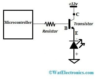
Interfacing NPN Transistors with Microcontrollers
NPN transistors are commonly used to switch ground-connected loads. Here’s a step-by-step guide on how to interface an NPN transistor with a microcontroller:

NPN Transistor Interfacing by a Microcontroller
Components Needed:
- NPN transistor (e.g., 2N3904)
- Microcontroller (e.g., Arduino)Voltage Rating:
- Load (e.g., an LED)
- Resistor (e.g., 220-1k ohm)
- Breadboard and jumper wires
Step 1: Connect the Components
- Place the NPN transistor on the breadboard and connect the collector (C) to the positive supply voltage (Vcc).
- Connect the emitter (E) to the cathode of the load (e.g., LED).
- Connect the anode of the load to ground (GND).
- Connect a current-limiting resistor between the base (B) of the transistor and a digital output pin on the microcontroller.
- Connect the microcontroller’s ground (GND) to the breadboard’s ground rail.
- Connect the microcontroller’s Vcc to the breadboard’s positive supply voltage.
Step 2: Write the Microcontroller Code
Write a simple code to control the transistor: The below code is a generic code that can be used for any microcontroller except that the functions digitalWrite and PinMode have to be defined using the # defines as per the port pins of the microcontroller.
void setup() {
pinMode(2, OUTPUT); // Set digital pin 2 as an output
}
void loop() {
digitalWrite(2, HIGH); // Turn the transistor on
delay(1000); // Wait for 1 second
digitalWrite(2, LOW); // Turn the transistor off
delay(1000); // Wait for 1 second
}Wait for 1 second }
This code will turn the transistor and the load (LED) on and off at 1-second intervals.
Step 3: Upload and Run the Code
Upload the code to your microcontroller and observe the LED turning on and off. You’ve successfully interfaced an NPN transistor with a microcontroller.
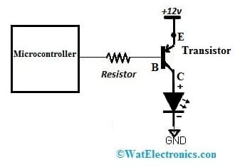
Interfacing PNP Transistors with Microcontrollers
PNP transistors are used to switch positive-connected loads. The process is similar to interfacing NPN transistors but with some polarity changes. Here’s a step-by-step guide on how to interface a PNP transistor with a microcontroller:

PNP Transistor Interfacing with a Microcontroller
Components Needed:
- PNP transistor (e.g., 2N3906).
- Microcontroller (e.g., Arduino).
- Load (e.g., an LED).
- Resistor (e.g., 220-1k ohm).
- Breadboard and jumper wires.
Step 1: Connect the Components
Place the PNP transistor on the breadboard and connect the emitter (E) to the positive supply voltage (Vcc).
- Connect the collector (C) to the anode of the load (e.g., LED).
- Connect the cathode of the load to the ground (GND).
- Connect a current-limiting resistor between the base (B) of the transistor and a digital output pin on the microcontroller.
- Connect the microcontroller’s ground (GND) to the breadboard’s ground rail.
- Connect the microcontroller’s Vcc to the breadboard’s positive supply voltage.
Step 2: Write the Microcontroller Code
- The code remains the same as the above one written for the NPN transistor. Whether it is an NPN or a PNP transistor the microcontroller code remains the same since it is only a change in the hardware connections.
- The code will turn the PNP transistor and the load (LED) on and off at 1-second intervals.
Step 3: Upload and Run the Code
Upload the code to your microcontroller and observe the LED turning on and off. You’ve successfully interfaced a PNP transistor with a microcontroller.
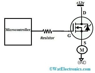
Interfacing N-Channel MOSFETs with Microcontrollers
N-channel MOSFETs are popular for switching high-power loads efficiently. Here’s a step-by-step guide on how to interface an N-channel MOSFET with a microcontroller:

N Channel MOSFET Interfacing with a Microcontroller
Components Needed:
- N-channel MOSFET (e.g., IRF540).
- Microcontroller (e.g., Arduino).
- Load (e.g., a motor).
- Resistor (e.g., 10k ohm).
- Diode (e.g., 1N4001).
- Breadboard and jumper wires.
Step 1: Connect the Components
- Place the N-channel MOSFET on the breadboard.
- Connect the drain (D) of the MOSFET to the positive supply voltage (Vcc).
- Connect the source (S) of the MOSFET to the positive terminal of the load (e.g., motor).
- Connect the negative terminal of the load to the ground (GND).
- Connect a current-limiting resistor between the gate (G) of the MOSFET and a digital output pin on the microcontroller.
- Connect the microcontroller’s ground (GND) to the breadboard’s ground rail.
- Connect a diode (anode to Vcc and cathode to the load’s positive terminal) to protect against back EMF when switching off inductive loads like motors.
Step 2: Write the Microcontroller Code
- Write a simple code to control the MOSFET:
- The code remains the same as the above one written for the NPN transistor. Whether it is an NPN or a PNP transistor or a MOSFET the microcontroller code remains the same since it is only a change in the hardware connections.
- The code will turn the MOSFET and the load (motor) on and off at 1-second intervals.
Step 3: Upload and Run the Code
Upload the code to your microcontroller and observe the motor turning on and off. You’ve successfully interfaced an N-channel MOSFET with a microcontroller.
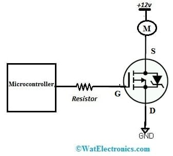
Interfacing P-Channel MOSFETs with Microcontrollers
P-channel MOSFETs are used to switch high-power loads with a positive connection. The process is similar to interfacing N-channel MOSFETs but with some polarity changes. Here’s a step-by-step guide on how to interface a P-channel MOSFET with a microcontroller:

P Channel MOSFET Interfacing to a Microcontroller
Components Needed:
- P-channel MOSFET (e.g., IRF9540).
- Microcontroller (e.g., Arduino).
- Load (e.g., a motor).
- Resistor (e.g., 10k ohm).
- Diode (e.g., 1N4001).
- Breadboard and jumper wires.
Step 1: Connect the Components
- Place the P-channel MOSFET on the breadboard.
- Connect the source (S) of the MOSFET to the negative supply voltage (Vcc).
- Connect the drain (D) of the MOSFET to the negative terminal of the load (e.g., motor).
- Connect the positive terminal of the load to the positive supply voltage.
- Connect a current-limiting resistor between the gate (G) of the MOSFET and a digital output pin on the microcontroller.
- Connect the microcontroller’s ground (GND) to the breadboard’s ground rail.
- Connect a diode (anode to the load’s positive terminal and cathode to Vcc) to protect against back EMF when switching off inductive loads like motors.
Step 2: Write the Microcontroller Code
The code is the same as the above one used for the NPN Transistor
Step 3: Upload and Run the Code
Upload the code to your microcontroller and observe the motor turning on and off. You’ve successfully interfaced a P-channel MOSFET with a microcontroller.
Troubleshooting and Tips
When Interfacing a Transistor with a Microcontroller, you may encounter issues such as unexpected behavior or damage to components. A few precautions need to be taken before connecting it to the microcontroller. Click on the link to know more about it: Precautions to be taken before connecting a transistor to the microcontroller.
Please refer to this link for Power Transistor.
Adding a resistor to the transistor’s base terminal is important to limit the excessive flow of current to the base terminal otherwise transistor can be damaged. To know more about this please refer to Choosing Base Resistance for Transistors in Electronic Circuits.