We know that a common substance like water is found naturally as a solid, liquid otherwise gas, and these are called states of matter. In solids, the arrangement of molecules can be done very close to each other because the molecules in the atoms move into the orbitals of adjacent atoms. In liquids, the arrangement of molecules is very close to each other whereas, in gases, the arrangement of molecules can be spread apart, so not very close to each other. Therefore, once atoms come together, … [Read more...]
What is Mho Relay : Working & Its Applications
In electronic circuits, a relay is a switch that is operated electrically to control the circuit with low power or one signal. First, relays are used as amplifiers in long-distance circuits. The function of the relays is to re-transmit the replicated signal out from one circuit to another circuit. Relays are electromechanical type, solid-state type, and reed type. Similarly, distance relays are one of the types and versatile relays used for distance protection, which depends on the distance … [Read more...]
What is Dynatron Oscillator : Circuit & Its Working
The oscillator is the foremost device in the domain of electronics and electrical applications. This crucial device is functioned to generate alternating current generally with the implementation of tuned circuits and some amplification equipment like thermionic vacuum tubes. Oscillators are specially employed to produce an increased range of frequency currents in the case of carrier waves in radio transmission probably are alleviated by linking the piezoelectric crystal (crucially quartz) with … [Read more...]
What is Stagger Tuned Amplifier & Its Working
The theory of modern electronics is based on amplification, which is achieved using the circuit called the amplifier circuit. As we know, the gain of the amplifier is not varied according to the signal frequency. Hence, to amplify and select the desired range of frequency a tuned amplifier circuit is needed. An amplifier circuit, which is used to amplify the desired range of frequency or a narrow band range of frequencies and rejects all other frequencies known as tuned amplifiers. To amplify … [Read more...]
What is Faraday’s Law : Formula & Its Experiment
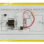
Faraday’s law of electromagnetic induction was the own discovery of two scientists Michael Faraday in the year 1831 and Joseph Henry in the year 1832. The first results from his experiments were released by Faraday. In his initial experiment, he found the principle of electromagnetic induction. In this, he rolled two metallic wire strips all across the iron ring. With this, he came to know the principle behind electromagnets. He believed that when there is the flow of current at one end of the w … [Read more...]
What is Flyback Converter : Design & Its Working
In the domain of electronics, we know that a regulator is a type of device or apparatus that can control the level of output power. There are many kinds of regulators available in the market which depends on the supply of power. But primarily, in the conversion process of DC to DC, there are mainly two kinds of regulators which are Linear and Switching. A linear type of regulator adjusts the output through a resistive voltage drop. With this, efficiency decrement and also power loss in the form … [Read more...]
What is a Voltage Follower : Circuit & Its Working
We all know that an operational amplifier is the analog type of circuit that considers differential voltage as input and provides a single-ended voltage as output. These op-amps are mainly employed in the voltage follower circuits. But the arrangement of the op-amp in the voltage follower imposes high risk and capacitive stacking of oscillations. These huge loads show more impact on the operational amplifier stability dependent applications. So, let us know how the arrangement can be done in a … [Read more...]
Wien Bridge Oscillator : Circuit Diagram & Its Operation
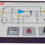
The electronic circuits used to generate periodic, oscillating signals such as sine waves or square wave,s or triangular wave are known as Oscillators. Oscillators take a DC signal and convert them into the required AC signal. These are used in numerous electronic devices where a clock signal is required. Some of the applications of oscillators are clock generators in calculators, computers, digital clocks, video games, etc... The signals generated by oscillators are also used in radio … [Read more...]
What is Synchroscope : Circuit & Its Working
In electrical power systems, a device is needed to measure the angle between any two AC systems like power networks or generators, which are synchronized with each other. To synchronize any two electrical systems, they must be operating at the same frequency at a phase angle of zero degrees. The synchroscope devices are used to measure the frequency and phase angle differences between two AC systems. If these differences are zero, then the two systems can be connected and synchronized with each … [Read more...]
What is EasyEDA : PCB Designing & Circuit Simulation
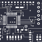
Before clearly knowing about the tool EasyEDA, let us first understand why this tool is required and how it saves cost and time in the domain of electrical engineering. People who work in the professions of the embedded engineer, electrical engineer, and electrical tester, have to design circuits, create boards and simulate the boards in an easier and simpler approach. So, EasyEDA is the online tool that crucially helps in the design of circuits. The initial version of this tool was appeared in … [Read more...]
- « Previous Page
- 1
- …
- 14
- 15
- 16
- 17
- 18
- …
- 25
- Next Page »