In the current digitized technology, there has been an enormous progression in the prospects of developing electronic circuits both in the digital and analog domains. In parallel with the development, the complexity also enhances at a quick rate. This enhancement in the complexity allows designers and developers to bring up modern engineered structures and designs in the electronics domain. And, in the scope of this evolution of sequential circuits took place. The article explains a clear scenario on the design and optimization of sequential circuits with maximum functionality and with the utilization of a minimum number of logic gates. Let’s go with a comprehensive approach to the functionality and performance of a sequential circuit.
Table of Contents
- What is a sequential circuit
- Types of sequential circuits
- Synchronous sequential circuits
- Asynchronous sequential circuits
- Sequential circuit examples
- Flip flop
- Master-slave JK flip flop
- Delay flip flop
- Toggle flip flop
- State in sequential circuits
- Applications of sequential circuits
- The need of sequential circuits
- Multiplexer: A sequential circuit or not?
- Register in sequential circuits
- FAQ’s
What is a Sequential Circuit?
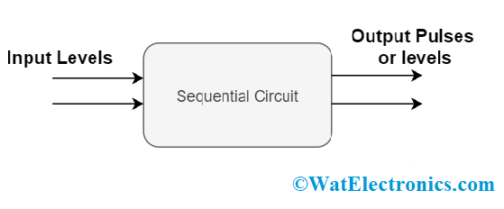
A sequential circuit is the assimilation of a combinational logic circuit and a storage element. With the applied inputs to the combinational logic, the circuit outputs are derived. These sequential circuits deliver the output based on both the current and previously stored input variables. The derived output is passed on to the next clock cycle. Sequential circuits consist of memory devices to store binary data. This binary information describes the current state of the sequential circuit. As sequential circuits work along with the combinational circuit, there are two types of combinational logic inputs where those are
- External inputs where these are not monitored by the circuit
- Internal inputs are the function of previous state output.
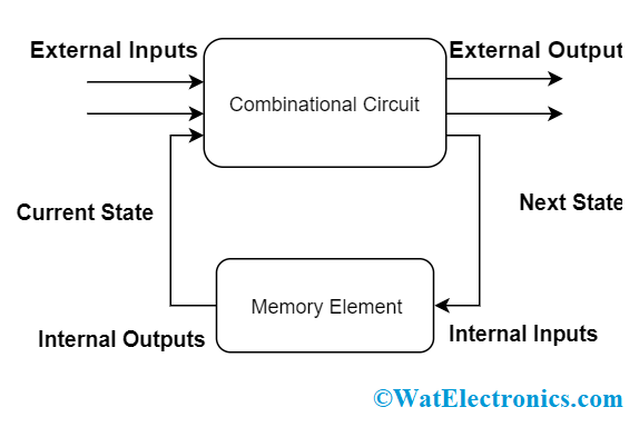
basic sequential circuit
As every digital and memory circuit is built based on the finite state machines, sequential circuits are implemented for the construction of these machines. So, these circuits hold more prominence in digital and electronics technology.
Types of Sequential Circuits
Here comes the discussion on the types of sequential circuits. These are of mainly two types and are discussed below:
1. Synchronous Sequential Circuits
2. Asynchronous Sequential Circuits
1). Synchronous Sequential Circuits
Synchronous sequential circuits use level inputs and clock signals as the circuit inputs having limitations on the circuit propagation time and pulse width to generate the output. The duration of the output pulse is like the clock pulse of the clocked circuits. Level output modified its state at the beginning of an input pulse and continues in that until the next clock pulse arrives. Until the arrival of the next pulse, these circuits perform no activity and so the operation is a bit slower than that of asynchronous circuits.
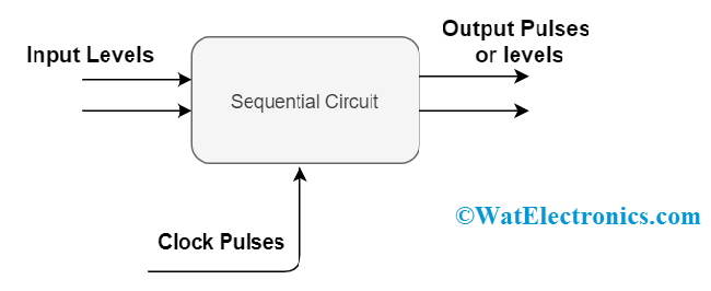
synchronous sequential circuit
Again, synchronous circuits are of two types clocked and unclocked.
a). Clocked Sequential Circuit
Clocked circuits use flip-flops and gated latches as the memory elements. The operation of the circuit is operated by the periodic clock pulses where these are connected to the clock inputs to synchronize all the internal modifications of the state.
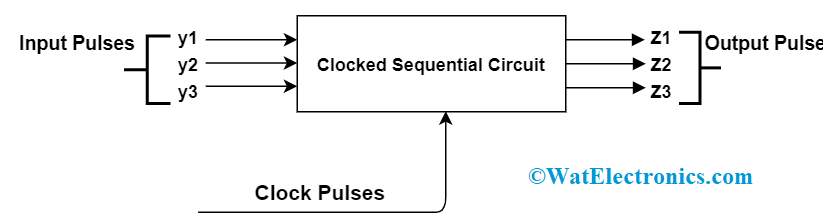
clocked sequential circuit
b). Unclocked Sequential Circuit
These circuits do not require any clock. The internal changes of the state are based on the pulse transitions between 0-pulse or 1 -pulse. This is designed to act in response to the pulses of specific time; the periodic signals in between the null and spacer signals.
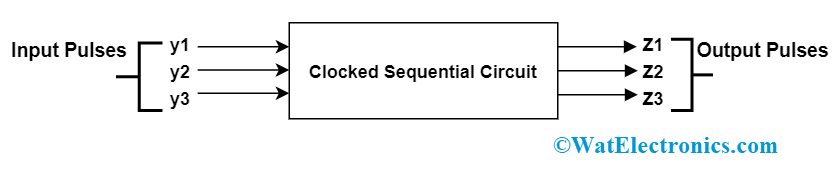
unclocked sequential circuit
Applications
Synchronous sequential circuits are implemented in the design of flip-flops, counters and to develop MOORE-MEALY state-controlled machines.
2). Asynchronous Sequential Circuits
Asynchronous sequential circuits perform their operation without depending on the clock signal but use the input pulses and generate the output. As there is no clock pulse dependency, these circuits can switch to the next state quickly when the input signal is changed. So, there is a faster operation with asynchronous sequential circuits.
asynchronous sequential circuit
Applications
Asynchronous sequential circuits are cost-effective to be used in small independent systems that need only a few elements. The communication between two elements, each hold its own independent clock, and this will be achieved by these circuits.
Sequential Circuit Examples
To describe there are various examples of sequential circuits. Few of the examples are
1). Flip Flop
It is an example of a sequential circuit that generates an output based on the sampled inputs and changes the output at certain intervals of time but not periodically. A flip flop is an edge-sensitive device.
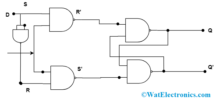
2). S-R Flip Flop
S-R flip flop is the combination of NAND gates and an enable input. The output is generated only when the enable input is in the active mode i.e. E=1. Whereas when E=0, there is no change in the output.
Block Diagram
The basic diagram of S-R flip flop is
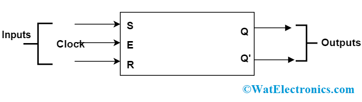
S-R flip flop
Circuit Diagram
S-R flip flop works in perfect condition when the circuit is connected as below
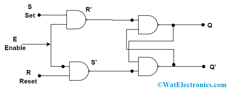
S-R circuit diagram
Truth Table
The output is clearly described in the below truth table
|
Inputs |
Comments |
||||
| E | S | R | Qn+1 |
Qn+1’ |
|
|
1 |
0 | 0 | Qn | Qn’ |
No Change |
|
1 |
0 | 1 | 0 | 1 |
Reset |
| 1 | 1 | 0 | 1 | 0 |
Set |
| 1 | 1 | 1 | × | × |
Indeterminate |
2). Master-Slave JK Flip Flop
This is the combination of two S-R flip flop’s connecting the output received from the second FF to the first FF. Master is considered as the positive level triggered one. But with the presence of clock line inverter, slave acts in response only to the negative level. So, when the clock is in ‘1’ state, the master becomes active and slave is in inactive mode. And when the clock is in ‘0’ state, the master becomes inactive and the slave is in active mode.
Circuit Diagram
Master-slave JK Flip Flop works in perfect condition when the circuit is connected as below
master-slave JK FF
Truth Table
The output is clearly described in the below truth table
|
Inputs |
Comments | ||||
|
E |
J | K | Qn+1 |
Qn+1’ |
|
|
1 |
0 | 0 | Qn | Qn’ | No Change |
| 1 | 0 | 1 | 0 | 1 |
Reset |
| 1 | 1 | 0 | 1 | 0 |
Set |
| 1 | 1 | 1 | Qn | Qn’ |
Toggle |
3). Delay Flip Flop
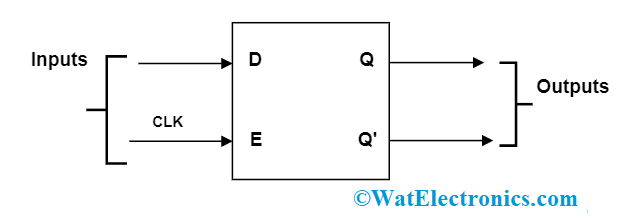
D flip flop is the combination of a simple SR flip flop with a NAND inverter which is connected in between the S and R inputs. D flip flop has one input and the input information appears at the output after some delay. So, this delay names this flip flop as Delay flip flop. Here, in the conditions of S = R = 0 or S = R = 1, then the input condition will not appear.
Block Diagram
The basic diagram of Delay flip flop is
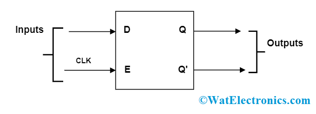
Delay FF block diagram
Circuit Diagram
Delay Flip Flop works in perfect condition when the circuit is connected as below
Delay FF circuit diagram
Truth Table
The output is clearly described in the below truth table
|
Inputs |
Outputs | Comments | ||
| E | D | Qn+1 |
Qn+1’ |
|
|
1 |
0 | 0 | 1 | Reset |
| 1 | 1 | 1 | 0 |
Set |
4). Toggle Flip Flop
Toggle flip flop is generally a JK FF with J and K inputs connected. Here only one input is present, and this flip flop is positive-edge triggered.
Block Diagram
The basic diagram of toggle flip flop is
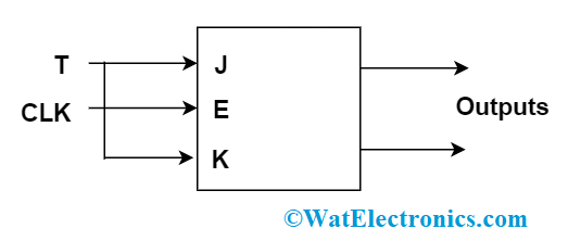
Toggle FF block diagram
Truth Table
The output is clearly described in the below truth table
|
Inputs |
Outputs |
Comments |
||
|
E |
T | Qn+1 |
Qn+1’ |
|
|
1 |
0 | Qn | Qn’ | No Change |
| 1 | 1 | Qn’ | Qn |
Toggle |
State in Sequential Circuits
As the output of sequential circuits is based on both the current and previous conditions, a storage element is more crucial in the sequential logic. So, the output of the entire storage elements in the sequential circuit and the binary information they contain is termed as the “State of the Circuit”. This state holds more importance in defining the output values. Also, the binary data describes the state of the sequential circuit at the time.
To be clear, a flip-flop is the memory element used to store binary data and has two states; where one state defines as “1” and the other state as “0”. So, information storage means to store the state.
Applications of Sequential Circuits
As the definition of the sequential circuit itself defines that these operate on the memory elements, the major application of these circuits is to build up the memory unit. From a small memory card to a huge computer memory, the application of the sequential circuit must be there. The extensive applications of sequential logic circuits are:
- Shift registers
- Flip flops
- Analog to digital and digital to analog converters
- Counters
- Clocks
- Used as registers inside microprocessors and controllers to store temporary information
- Applied in programmable devices such as CPLD, PLD, and FPGA
The Need of Sequential Circuits
Well, these days digital electronics observed widespread progression and of the numerous elements, the one that received extensive prominence is sequential circuits. These sequential circuits stand as fundamental building blocks. We need these circuits to gain improved performance and they are employed in the operations that work with less power. Moreover, the speed of operation in processing the activities also gained the sight of many.
Multiplexer is a Sequential Circuit or Not?
Multiplexers are not sequential circuits. They are the combinational circuits having 2n inputs and a single output.
Register in Sequential Circuits
So, we have discussed the operation of how a sequential circuit works. As it presents the output based on the past and current inputs, There has to be one element to store the past information, and the one that is used to store the data is “Register”. A register is a device used to store multiple bits of information.
Know more about Time Division Multiplexing MCQs.
FAQ’s
1. Do sequential circuit work on memory elements?
Yes, Sequential circuits deliver output based on the past state inputs and current input where past information is stored in a memory element.
2. What are the three main classifications of sequential logic circuits?
The basic classification of sequential circuits is event-driven, pulse driven, and clock-driven.
3. What makes the difference between flip flop and latch?
The basic difference between the two is the process of modifying their state. The latch does not work with clock input whereas flip flop has clock input.
4. What is the basic example of event-driven circuits?
A digital alarm is the fundamental example of an event-driven sequential circuit where it is activated by the event that raised up the alarm.
5. What are the two different conditions of an asynchronous circuit?
Asynchronous circuits exist in stable and unstable conditions. When the subsequent state of the circuit is the same as the current one, it is in stable condition. While, when the input gets modified, the circuit moves into an unstable condition.
Please refer to this link to know more about Priority Encoder.
Please refer to this link to know more about Digital Circuits MCQs & Analog Circuits MCQs.
With the enhanced operations and implementations using the sequential circuit, these are almost present in every digital circuit that is in use today. Enhanced prominence of sequential circuits also enhances the prominence of digital electronics. Have a look at all the other operations of sequential circuits, and how they are implemented?