The fixed output voltage regulator is an integrated circuit from the LM78xx series. This series mainly includes LM7805, LM7812, LM7824, LM7809, etc. So these regulators are frequently used in electronic circuits to provide a stable output voltage for different input voltages. The term 78 in this series of regulators signifies a positive voltage regulator whereas the remaining number indicates the output voltage provided by the IC. But these ICs suffer from huge heat loss, thus a Heat sink is suggested for different projects that utilize more current. This article provides one of the fixed output voltage regulators IC like LM7815 IC, pin-out, specifications, and its applications.
What is LM7815 IC?
LM7815 is a fixed-voltage regulator IC available in TO-220FP, TO-220, D2PAK, and TO-3, packages. This voltage regulator IC provides a 15V positive voltage-like output to supply a suitable power source for nearly all TTL components. This regulator IC uses a fluctuating input voltage and generates a stable 15v production. So this regulator IC is designed to be used in a wide range of applications for powering different electronic circuits that need a consistent 15V supply. LM7815 IC is very popular and easy to utilize without external components or circuitry for voltage regulation.
How LM7815 IC Work?
The LM7815 IC works like a fixed-voltage positive voltage regulator, so it provides a stable 15V voltage instead of fluctuations within the input voltage (or) load conditions. This IC uses internal circuitry like a reference voltage, a pass transistor, and an error amplifier that constantly adjusts the output voltage by keeping 15 volts to a set level. So this voltage can be compared with the reference voltage in the IC.
The LM7815 IC compares the o/p voltage with a reference voltage of normally 1.25 volts. So the error amplifier produces an error signal that signifies the variation between the two voltages. After that, the pass transistor regulates depending on the error signal. The pass transistor performs more current to enhance the output voltage if the output voltage is very low. If the o/p voltage is very high, then the pass transistor performs less current to reduce the output voltage.
LM7815 IC Pin Configuration:
The LM7815 IC pin configuration is shown below. This IC includes three pins which are explained below.
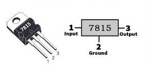
LM7815 IC pin Configuration
- Pin-1 (Input (V+)): It is an unregulated input voltage pin that provides input supply to the IC.
- Pin-2 (Ground): It is a GND pin of the IC.
- Pin-3 (Output (Vo)): It is an output-regulated pin of a voltage regulator IC.
Features & Specifications:
The features and specifications of LM7815 IC include the following.
- LM7815 is a fixed-voltage regulator IC.
- It is available in the TO-220 package.The mounting type is Through the hole.
- Its output current ranges from 1Amp to 1.5Amps.
- This IC has an in-built short circuit, shut down, and overheat shutdown function.
- Its fixed and stable output voltage is 15V DC
- Input voltage ranges from 7 to 35V DC.
- Its standby current is 8mA only.
- Its quiescent current ranges from 5 to 8mA
- Line regulation is 0.1% and load regulation is 0.5%.
- Voltage dropout at 1A is 2V.
- PSRR at 120Hz is 70dB.
- This IC’s operating temperature ranges from -40°C to 125°C.
Equivalents & Alternatives
Equivalent to LM7815 ICs are UA7815, LM2940CT-15, L7815, LM340AT–15, KA7815, LM340T–15, LM7915, etc. Alternatives to LM7815 ICs are; LM340, LM317, LM7915, UA7815 KA7815, L7815, etc.
How to use LM7815 IC securely in a Circuit for a Long Time?
To utilize an LM7815 voltage regulator IC securely within a circuit, then the three terminals of the IC must be connected properly. A 0.33uF ceramic input capacitor must be close to the input pin whereas a 0.1uF output ceramic capacitor to the output pin to enhance stability & filter out voltage fluctuations. Make sure that always input voltage is always higher than the preferred 15V output to keep away from damage.
Place the ceramic capacitors very close to the IC voltage regulator IC terminals for stability and optimal performance. Always utilize a heat sink for stable, good, and long-term performance within your circuits by protecting them from overheating, short circuits, etc. Do not drive any load > 1.5A and apply input voltage > 35V. This voltage regulator must be operated in temperatures from 0 degrees Celsius to +125 degrees Celsius. It must be stored from -65 degrees Celsius to +150 degrees Celsius temperature.
15Volts 1Amps Power Supply Circuit with 7815 IC
A 15Volts DC power supply circuit with LM7815 IC is shown below. This is an electric power converter that changes the energy from one form to another. These ICs are mostly used to design power supply circuits because of their benefits like smaller size, cheap, and need few external components. This voltage regulator IC maintains the voltage stable by protecting from overload and short circuits.
The required components to make this power supply circuit mainly include; LM7815 IC, 230V /18V, 1A step-down transformer, 1N7004 diode bridge, polar capacitor 2200uF, 35V, 330nF, 100nV non-polar capacitors, aluminum heat sink, breadboard, and connecting wires.
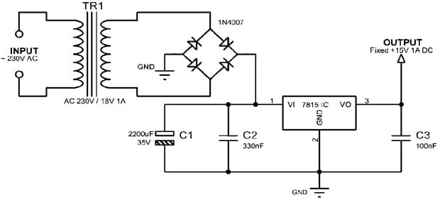
15Volts 1Amps Power Supply Circuit
Working
This power supply circuit using 7815 IC uses 230V AC input supply and provides maximum positive 15V 1A DC output. The 15V 1amp power supply circuit with LM7815 voltage regulator IC is shown below. The significant component used in this regulated power supply circuit is an LM7815 positive voltage regulator IC. This is a monolithic IC designed to provide fixed 15V.
This 15V power supply circuit works as; whenever the circuit receives 230V AC input to the primary of a T1 transformer, then it steps down the voltage to 18v 1amp AC on its secondary winding. After that, this step-down AC voltage rectifies and changes AC to DC voltage with a full bridge BR1 rectifier in the circuit. So a C1 capacitor in the above circuit smoothens and filters the DC voltage.
Thus, this 18Volts DC voltage can be changed by the LM7815 voltage regulator IC to 15V constant DC voltage, so extra voltage can be converted into heat so a suitable heat sink must be used with this IC. The C2 and C3 capacitors in this circuit are used to decrease the ripple noise. So this power supply circuit finally provides 15v 1amp DC output.
12V Car Battery Charger Circuit with LM7815 IC
This 12V car battery charger circuit with LM7815 IC is shown below. This circuit is used to charge a common battery of a car at maximum current and reduces battery voltage whenever it reaches its maximum charging condition.
The required components to make this circuit mainly include LM7815 IC, resistors like 0.33-ohm resistor, 10 watts, 8.2-ohm resistor, 2 watts, electrolytic capacitor – 10,000uF / 100V, 5 amps SB560 diodes, 12V car battery and 120 / 240VAC transformer. Connect this circuit as per the circuit shown below.
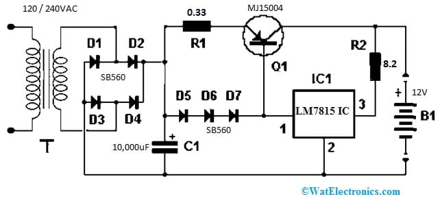
12V Car Battery Charger Circuit with LM7815 IC
Working
The set of three diodes in the above circuit are connected in series and they are parallel to the R1 resistor. The Q1 transistor’s EB junction creates a stable current source. Here, the R1 resistor sets the current supply throughout the transistor. In the above circuit, every diode has a 0.7-volt voltage drop. So the estimated current throughout the R1 resistor can be I = V / R => 1.4 volts /0.33 ohms => 4.2 Amps.
The voltage regulator’s main function is to keep the current source active. Whenever the battery is charged completely then almost there is no current supply throughout the IC & the Q1 transistor will go into cut-off due to no current supply throughout its base terminal.
The R2 resistor in this circuit limits the current supply at the output and through the IC1 regulator and the R2 resistor allows the current supply to flow throughout IC1. Thus base terminal of the Q1 transistor has a current that is saturated until the o/p voltage reaches around 13.5V.
Whenever the voltage supply achieves 13.5V, then the current starts reducing and it will decrease continuously when the voltage supply increases continuously. So reducing the R2 value increases the last battery charge voltage. Thus, the battery can also be charged at a lower voltage by placing one diode or additional diode in series in the current flow direction on one of its terminals. So this causes a voltage drop of around 0.7V for each diode.
Advantages and Disadvantages
The advantages of LM7815 IC include the following.
- LM7815 IC is simple to use.
- It provides a 15V stable output voltage.
- They carry significant currents with a suitable heat sink to power many devices.
- It has short-circuit protection and thermal overload protection which extends the lifespan of components & protects them.
- These are easily accessible, affordable & widely available.
- This IC occupies less space due to its small size.
- It requires minimum external components for its operation.
The disadvantages of LM7815 IC include the following.
- Its loss is large and poor efficiency whenever there is a huge variation between the input & output voltage.
- It generates a huge amount of heat when the variation between the two voltages is large.
- Step-down operations are possible only.
Applications
The applications of LM7815 IC include the following.
- LM7815 voltage regulator IC provides a 15V stable power supply to different microcontrollers utilized in embedded systems.
- It is used to power a variety of sensors that need a 15Volts operating voltage.
- It is used in power supply circuits, op-amp circuits, voltage step-down circuits, voltage converter circuits, motor drivers, solar power supplies, and battery chargers circuits.
- The 7815 IC can be used in certain circuits next to other components to make an adjustable output.
- This IC can work as a current limiter to prevent extreme current supply from harming sensitive components.
- This IC can work within a dual supply configuration, wherever it provides a positive regulated voltage next to a negative regulator like 7915 IC.
- LM7815 IC can be used as a constant voltage regulator to power electronic sensors & microcontrollers.
- It can be used as a regulated dual supply within electronic circuits, and output reversal polarity protection circuits.
- This can be used in different electronic devices like battery chargers, industrial automation systems, audio amplifiers, etc.
Please refer to this link for the LM7815 IC Datasheet.
Thus, this is an overview of LM7815 IC, pin-out, features, specifications, and its uses. The LM7815 is a fixed voltage regulator IC, designed to provide +15V stable output voltage in a variety of electronic systems like power supplies, industrial control systems, automotive systems, and many more. So it is an essential and versatile component in many electronic systems that can power sensors and microcontrollers. Thus, it can be used as a voltage stabilizer or current limiter. This IC can be substituted with different ICs like LM7915, LM317, LM340-15, etc. So this IC can be protected from extreme heat by using a heat sink. Here is a question for you, what is LM340 IC?