A basic diode has various applications it includes rectifiers in it as well. Rectification can be done through the basic diode. It may be current or voltage the AC values will be converted into DC. The basic property of the diode is that it can establish the path for the flow of current in one direction that is possible during forwarding bias. However, during reverse bias, the diode remains in non-conducting mode. It doesn’t participate for the establishment of the path for the flow of current. Hence this made the diode to utilize it for rectification. This article covers the basics of Rectifier, its working theory, functioning, circuit diagram, equations and furthermore its applicstions.
What is Rectifier?
Definition: A normal diode with its junction formed due to p-type and n-type interaction is utilized for the purpose of conversion of alternating currents into direct currents. This process is referred to as rectification and the respective circuitry designed for rectification is defined as a rectifier.
As the property of diode suggests, whether a diode with the junction as p-n can operate in forwarding bias or block the flow during reverse bias.
The diode in forwarding bias is in conducting mode because the p-type is connected to the positive part of the supply and the n-type is connected to the negative part of the supply. There is the movement of electrons from the n-side towards the p-side and the holes movement can be evident from the p-side towards the n-side.
As these are the majority charge carriers from both sides. Their movement makes to generate the current that is referred to as forwarding current.
If the diodes p-type is connected to the negative part of the supply and n-type is connected to the positive part of the supply. This type of connection makes the diode to be in reverse bias.
Hence the majority of the charge carriers get attracted towards the respective terminals of the battery. Then the existence of minority carriers makes the presence and the reverse saturation current flows in the circuit.
But the reverse current in the diode is because of the influence of minority charge carriers. So that it can be neglected. Hence these conditions are utilized and make the diode as the part of the application.
These are the basic biasing techniques that make a part of the rectifier theory.
Functioning
Biasing basically done by using the supply in terms of DC but as per the consideration of rectifier, the terms must be realized by considering AC as the supply. As the representation of AC and DC is already known, AC in terms of sinusoidal wave and the DC representation is done with a straight line.
The upper part of the wave denotes the positive side of the supply and the lower part denotes the negative side of the supply. Positive half is the representation of the forward bias voltage of DC and the negative half representation will be of the reverse bias voltage of DC.
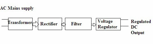
general diagram of power supply
The waveform of AC is not constant it is a variant of time. As it reaches the positive peak value it tends to degrade the same will be followed for the negative value after reaching zero again it will come back to zero lines.
Now let us begin the working of rectifier by applying AC as the input. For the positive half of the cycle, the diode acts in forward bias mode. Hence the path is established for the movement of charge carriers.
Once the negative part of the cycle is applied to the diode it blocks the value of the current because the movement of minority charge carriers in it can be neglected. Simply one can define the working of the diode as conducting in forward bias and blocking in reverse bias to the flow of current.
Hence the flow of current is evident during the positive part of the cycle applied to the diode. The output obtained it must be converted from AC into DC. In this way the basic diode functions as a rectifier.
General Representation of Power Supply
But these rectifiers generally don’t produce any pure form of DC. It consists of an impure form of AC components in the obtained output. Hence these AC components are referred to as ripples. These ripples can be removed by using a filter connected across the rectified output in order to obtain the smoothening effect. It is said to be maximum efficient if its ripple factor value is at a minimum.
Rectifier Circuits
Basically, the rectifier circuits can be classified as
- Half Wave Rectifiers
- Full Wave Rectifiers
Rectifier Circuit of Half Wave
A half-wave rectifier is a basic circuitry with a single diode used in it. This connected to a series AC supply as well as a series load resistor. It follows the property of the diode by conducting to the positive cycle. This consideration makes this circuitry a simple one to analyze.
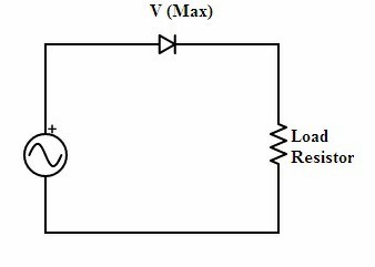
half-wave rectifier
Rectifier Equations of Half Wave Rectifier
The average value of voltage,
Vavg= Vm/π
The average value of the current can be given as
Iavg=Im/π
The value of RMS voltage can be given as
Vrms=Vm/2
The value of RMS current can be given as
Irms=Im/2
The ripple factor value of half-wave rectifier is
Ripple Factor=1.21
The efficiency value of the rectifier is given as
maximum efficiency=40.6%
The form factor value is
form factor=1.57
The above are some of the rectifier equations that relate to the half-wave rectifier.
Rectifier Circuit of Full Wave
A full-wave rectifier can be classified as a center-tapped and bridge rectifier circuits. It is more efficient compared to that of half-wave. It can utilize both the cycles so that the loss in power is minimum.
Centre Tapped Full Wave Rectifier Circuit
It consists of a center-tapped transformer with two diodes connected with a resistive load. The positive point of it is that one diode responds during one part of the cycle and the other during another part of the cycle. In this way, there is no loss of the output power.
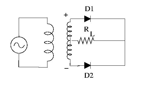
full-wave rectifier center-tapped
Centre Tapped Rectifier Circuit
The drawback for this kind of rectifier is that the usage of the center-tapped transformer makes it costly. Hence another circuit referred to as bridge rectifier has been designed.
Bridge Rectifier Circuit
A rectifier with four diodes connected in such a way that it follows bridge topology referred to a bridge rectifier. It has been drawn to overcome the drawback of the center-tapped rectifier.
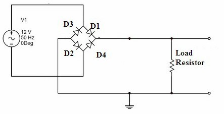
full-wave rectifier (bridge)
Diodes D1 and D2 acts for one part of the cycle and D2 and D3 responds to the other part of the cycle so that it can utilize both the halves of the cycles and makes the circuit less costly by using a normal transformer.
Rectifier Equations for Full Wave
The average value of the voltage can be given as
Vavg=(2Vm)/π
The average value of the current can be given as
Iavg=(2Im)/π
The RMS value of the voltage is given as
Vrms=Vm/√2
The RMS value of the current is given as
Irms=Im/√2
The maximum efficiency of the full-wave rectifier can be given as
E=81.2%
The form factor value is
form factor=1.11
The above are some of the equations of the full-wave rectifier. Furthermore, Rectifier Equations are
1) Average Value
The instantaneous value for the signal considered its average for the arithmetic is referred to as the average value of the given rectifier.
Avg.value=(area present under the curve)/( complete value of the base )
2) RMS Value for the Rectifier
It can be referred to as the square root of the respective means.
RMS value of the given signal=√((area present under the respective curve squared)/( length of the base) )
The heat produced by the AC signal RMS value is the same as that of the flowing DC current of the equal value through similar resistance.
3) Peak Factor of the Rectifier
The ratio between the maximum peak value for the applied signal to the RMS value of the respective signal is referred to as the peak factor.
Peak factor=(max.peak value)/(RMS value )
4) Form Factor of the Rectifier
The ratio of the RMS value of the applied signal to its average value is referred to like the form factor.
Form factor=(RMS value of the input signal)/( average value of that signal )
5) Ripple Factor
It can be defined as the ratio of the AC component’s RMS value to the DC component present at the output.
γ=VAC/VDC
The final equation for the ripple factor is
γ=√((VRMS/VDDC )^2– 1)
6) Efficiency of the Rectifier
The ratio between the generated DC output power to the applied input power gives the efficiency of the respective rectifier.
E=PDC/PAC
Advantages
The basic advantage of the rectifier is that it can convert alternating current into direct current.
Applications
- Because of its property of rectification, it can be utilized as a part of the power supply circuitry.
- It can be utilized in power supply units with switching-mode technique.
- During the detection of the amplitude for the modulated radio signals rectifiers are used.
- In order to supply the voltage in a polarized manner for the purpose of wielding rectifiers are used.
Hence the overview for the basic rectifiers is given. It can be the useful part for the application of the power supply unit but it can’t be used in practical applications without applying it to a filter Now can you tell are the rectifiers useful in ADC conversions or any further way is there to convert it?