In the world of electronics, the integration of microcontrollers and transistors has revolutionized the way we control and manage electronic circuits. Transistors serve as essential switches or amplifiers, while microcontrollers provide the brains behind countless electronic applications. However, this harmonious relationship demands careful attention to detail and a clear understanding of potential risks. When connecting a transistor to a microcontroller, it is crucial to take various precautions to ensure the reliable operation of the circuit, safeguard both components from damage, and optimize overall performance. In this article, we delve into a comprehensive guide of precautionary measures, illuminating the critical factors and considerations that must be taken into account to create robust and functional transistor-microcontroller interfaces.
Precautions for Connecting a Transistor to Microcontroller
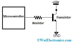
- Verify Pinouts: Double-check the pin configuration of the transistor and the microcontroller to ensure that you have connected the right pins. Incorrect connections could lead to unexpected behavior or damage to the components.
- Current and Voltage Ratings: Make sure the load you are controlling (e.g., LED, motor, relay, etc.) does not exceed the maximum current and voltage ratings of both the transistor and the microcontroller’s digital output pins. Exceeding these ratings can damage the components.
- Use Current-Limiting Resistors: When connecting an LED as the load, always use a current-limiting resistor to prevent excessive current flow through the LED, which could lead to LED burnout.
- Base Resistor Calculation: Calculate the appropriate value for the base resistor (Rb) to limit the current flowing into the Base of the transistor. Rb can be calculated as (Vmicro – Vbe) / Ibase, where Vmicro is the output voltage of the microcontroller, Vbe is the Base-Emitter voltage drop (typically around 0.7V for silicon transistors like MMBT3904), and Ibase is the desired Base current. This helps avoid overdriving the Base and potentially damaging the transistor.
- Flyback Diode for Inductive Loads: If you are controlling an inductive load (e.g., a motor or relay), consider using a flyback diode (also known as a snubber diode) in parallel with the load to protect the transistor from voltage spikes generated when the inductive load is switched off.
- Avoid Static Discharge: Handle the components carefully, and avoid static electricity discharge, as it can damage sensitive electronic components like the microcontroller and the transistor.
- Testing and Debugging: Always test the circuit with lower current/voltage loads first and monitor its behavior before connecting higher power loads. This will help identify any issues and prevent potential damage during testing.
- Temperature Consideration: Consider the power dissipation and operating temperature of the transistor, especially if you are switching higher currents. Ensure that the transistor’s power dissipation rating is not exceeded to prevent overheating.
- Heat Sinks: In cases where the transistor might dissipate a significant amount of power, consider using a heat sink to keep the temperature within safe limits.
- Fuse Protection: Depending on your application, consider adding a fuse in series with the load to protect the circuit from excessive current.
The precautions mentioned above generally apply to most microcontrollers when interfacing with a transistor, particularly when using the transistor as a switch to control external loads. However, there can be some slight variations or additional considerations depending on the specific microcontroller and its characteristics. Here are some points to keep in mind:
- Microcontroller Output Voltage and Current: Ensure that the microcontroller’s output voltage and current levels are compatible with the requirements of the base current for the transistor. Some microcontrollers operate at lower voltages (e.g., 3.3V), and their output pins may have limited current sourcing capabilities compared to those operating at higher voltages (e.g., 5V).
- GPIO Pin Configuration: Verify the GPIO (General Purpose Input/Output) pin characteristics of the microcontroller, such as its maximum current sink/source capabilities and whether it has internal pull-up or pull-down resistors that could affect the transistor’s behavior.
- Input/Output Protection: Some microcontrollers have built-in protection features for their GPIO pins, like overcurrent protection or ESD (electrostatic discharge) protection. Understanding these protections can be helpful in designing a robust circuit.
- PWM Outputs: If you plan to use pulse-width modulation (PWM) to control the load’s intensity or speed, consider how the transistor’s switching speed aligns with the PWM frequency. Some transistors might not be suitable for high-frequency PWM applications.
- Microcontroller Grounding: Pay attention to the grounding scheme of the microcontroller and the load circuit. Proper grounding is crucial to avoid ground loops and potential noise issues.
- Microcontroller Power Supply: Ensure the microcontroller is adequately powered and stable to avoid erratic behavior, especially if the load’s switching generates electrical noise.
- Microcontroller Power Dissipation: In applications where the microcontroller directly drives the load and not just the transistor, consider the overall power dissipation of the microcontroller.
- GPIO Configuration and Initialization: Depending on the microcontroller, you might need to configure the GPIO pins correctly and initialize them in the code before use.
Please refer to this for How to Select a Transistor.
Microcontroller Operating Modes: Some microcontrollers have different operating modes (e.g., sleep modes) that could affect the behavior of the output pins and, consequently, the switching behavior of a transistor.
Whether you’re a seasoned electronics enthusiast or a curious beginner, arming yourself with this knowledge will pave the way for successful, safe, and efficient electronic projects.