DC-DC switching regulators are used to change the voltage efficiently from one DC to another. So, high-efficiency DC to DC regulators come in three basic topologies step-up or boost, step-down or buck & step-up/step-down or buck/boost. The boost converter is utilized to generate a higher DC output voltage, the buck converter is used to produce a low DC output voltage & finally, the buck or boost converter is utilized to produce an output voltage greater than, less than, or equivalent to the input voltage. Thus, this article elaborates on one of the steps up DC to DC switching regulators like LM2621 IC, working and its applications.
What is LM2621 IC?
The LM2621 IC is a step-up DC to DC switching regulator which is available in a VSSOP-8 package. This IC can be utilized in low-input voltage systems, cellular phones, and battery-powered circuits. So the LM2621 IC operates from 1.2 V to 14 V input voltage and changes it into a regulated output voltage ranging from 1.24 V to 14 V. This switching regulator achieves up to 90% efficiency and its switching frequency can be adjustable up to 2 MHz. Thus, this IC has a low quiescent current which helps in improving battery life in stand-by & shutdown. The LM2621 IC has a thermal protection circuit and an in-built peak switch current limit.
LM2621 IC Working
The LM2621 IC works as a step-up DC-DC switching regulator which uses a low input voltage and provides high output voltage. So it can be used particularly in battery-powered applications wherever a higher voltage is required from a battery. This is a step-up and high-efficiency DC-DC switching regulator used for battery-powered and low-input voltage systems.
This IC accepts from 1.2 V to 14 V input voltage and changes it into a regulated output voltage that can be adjusted from 1.24 V to 14 V. So this IC is useful, particularly in applications wherever the input voltage is under the preferred output voltage like handheld electronics, power backup systems & portable devices.
LM2621 IC Pin Configuration:
The pin configuration of LM2621 IC is shown below. So this IC includes 8 pins which are discussed below.
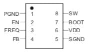
LM2621 IC Pin Configuration
- Pin-1 (PGND): The PGND is a power ground pin that carries high pulsed currents like current supply throughout a power transistor (or) power driver stage’s pulsed currents.
- Pin-2(EN): It is an enable or a logic-level input pin utilized to allow or stop device switching & low quiescent current when disabled.
- Pin-3 (FREQ): This is the switching frequency pin of an IC that ranges from kHz to MHz. So the switching frequency is the speed at which the DC voltage is switched ON & OFF throughout the PWM process.
- Pin-4 (FB): This is the feedback pin of the IC that allows the o/p voltage to be calculated & regulated through the IC.
- Pin-5 (SGND): This is the signal GND pin of the device. So it is a GND connection that other signals utilize as a reference. Thus, it is frequently used to connect the GND from a powered system.
- Pin-6 (VDD): VDD stands for voltage at the drain pin that supplies a +ve power supply voltage to the IC.
- Pin-7 (BOOT): This pin is used to choose boot modes. So the number of these pins can be used to decide the number of available boot options.
- Pin-8 (SW): It is a switch pin of IC which is a digital o/p pin on a joystick that can be connected to a push-button switch.
Features & Specifications:
The features and specifications of LM2621 IC include the following.
- LM2621 IC is a step-up DC to DC switching regulator.
- It is available in a small VSSOP-8 package.
- Its switching frequency is up to 2 MHz.
- Its input voltage ranges from 1.2V to 14V.
- Its adjustable output voltage ranges from 1.24V to 14V.
- Load current is up to 1Amps.
- Its internal MOSFET is 0.17 Ω.
- Regulator efficiency is up to 90%.
- The typical operating current is 80 µA.
- Its typical quiescent current is 85 µA.
- Its maximum o/p current mainly depends on input voltage & inductor choice.
- The guaranteed current supply in the shutdown is <2.5µA.
- Its operating temperature ranges from -40 to 85 °C.
Equivalents & Alternatives :
Equivalent to LM2621 ICs are LM2623, LM27313, LM2733, LM322, TPS61170, etc. So alternative step-up DC to DC switching regulators are; MT3608, XL6009, MC34063, ME2108A50PG, LM2733, XL6009E1, etc.
1.5 Volts to 5 Volts Converter Circuit with LM2621 IC
An electronic circuit design powered by a battery has always one issue which is the necessity of different levels of voltage & current. So, some input devices like sensors (or) output actuators may need higher voltage as compared to battery power sources. To meet these specifications and requirements here we are designing a 1.5V to 5V converter circuit with LM2621 IC.
Generally, DC-DC boost converter is used in various small and portable battery-powered devices however the trouble is these converters drain the battery quickly and won’t provide correct output current levels. So the following circuit provides output current up to 500mAmps and its usual operating current will be 80µA.
The required components to make this converter circuit mainly include; capacitors like 39pF, 100nF, 22µF & 68µF, resistors like 50KΩ, 150KΩ, 200KΩ & 500Ω, 6.8µH inductor, MBRS140T3G diode, LM2621MM IC, 1.5V input battery and connecting wires. So, connect this circuit as per the diagram shown below.
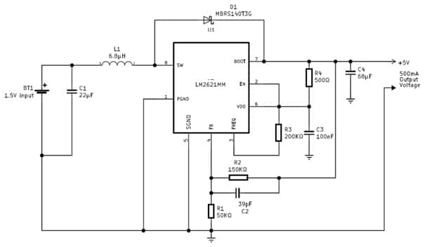
1.5 Volts to 5 Volts Converter Circuit with LM2621 IC
Working
This 1.5Volts to 5Volts converter circuit works with a 1.5V AA (or) AAA battery. So it can increase any 1.5Volts input supply to 5 volt 500 mA o/p. Thus, this circuit needs a few easily available components only. This circuit must be used with an external battery holder to use with AA (or) AAA battery.
The LM2621 IC used in this circuit is a high-efficiency and step-up DC-DC switching regulator, used for low input voltage and battery-powered systems. This IC accepts input voltage from 1.2V to 14V and changes into regulated o/p voltage. So this voltage can be changed between 1.24V to 14V. The switching frequency of this IC in this circuit operates in 2MHz which delivers up to 1A load current.
Advantages & Disadvantages
The advantages of LM2621 IC include the following.
- The LM2621 IC achieves up to 90% efficiency.
- It has a low quiescent current that reduces current supply to 80 µA and < 2.5 µA within shutdown mode.
- It is available in a small VSSOP-8 package.
- It has an adjustable switching frequency that ranges from 300 kHz to 2 MHz.
- This IC has an in-built voltage reference, thermal limit, and current limit.
- This IC operates with as low as 0.65 V input voltage.
- It is designed to be utilized within battery-powered systems where small size, low quiescent current, and low profile are required.
The disadvantages of LM2621 IC include the following.
- These are more expensive as compared to linear regulators.
- These ICs are more complex and need different skills to design & implement.
- They generate noise because of switching operations, which can introduce EMI (or) switching noise.
- This IC is compliant with EMI regulations which can be labor-intensive & time-consuming.
- These regulators need attention to component position grounding & trace routing to reduce the switching noise effects.
- These ICs may malfunction.
Applications
The applications of LM2621 IC include the following.
- The LM2621 step-up DC-DC converter IC is used where low input voltage & battery power are required like cellular phones.
- It has a low quiescent current that helps in improving battery life in stand-by & shutdown modes.
- This IC is used in portable electronics, low-power wireless modules, battery-powered devices, power backup systems, etc.
- This is a high-efficiency DC-DC step-up switching regulator, so used in battery-powered & low-input voltage systems.
- It is a battery-powered device & low input voltage system.
- This switching regulator is used to change low i/p voltages into regulated o/p voltages. So it is utilized within battery-powered systems (or) systems that have low input voltages.
- The LM2621 IC is particularly used in applications where the input voltage is under the preferred output voltage like handheld electronics, power backup systems, portable devices, etc.
Please refer to this link for the LM2621 IC Datasheet.
Thus, this is an overview of LM2621 IC, pin-out, features, circuit, working, pros, cons, and its uses. This is a general purpose, step-up, and high efficiency based DC to DC switching regulator used in battery-powered devices & low input voltage systems. So, here is a question for you, what is MT3608 IC?