The name for DeMorgan’s laws was named after a British logician and mathematician Augustus De Morgan. The influence behind the invention of these laws was the algebraization of logic carried out by George Boole and later strengthened by DeMorgan’s claim to the find. Even though there were many observations made on these principles by Jean Buridan, William of Ockham, and many others, the credit was given for DeMorgan where he specified the laws in the form of contemporary formal logic and integrated them into the logical language. And today, this article explains what are DeMorgan’s laws, what are its truth tables, formula, state & proof DeMorgan’s theorem and applications?
What is Demorgan’s Theorem?
DeMorgan theorem is crucially important in solving various kinds of Boolean algebraic expressions. These laws are pair of transformation principles used in solving complicated logical expressions in high circuit designs and in computer programming. This theorem states the similarity between gates having identical inverted input and output.
As we know that Boolean algebra defines a logical circuit by using specific guidelines having 0’s and 1’s that represents input and output condition in a digital format. So, using 0’s and 1’s, truth tables and logical expressions are created and operations like AND, OR, and NOT are performed.
The rules of DeMorgan are developed depending on the boolean expressions of AND, OR, and NOT gates. DeMorgan’s theorem statement is that reversing the output of any gate gives the result a similar function as the opposite kind of gate that is AND versus OR having A and B as two inverted variables.
DeMorgan’s First Theorem
The first theorem of DeMorgans’ law defines that the inverted result from AND operation is the same as the OR operation of the complement of each variable where the result equals NAND operation.
So, DeMorgan’s theorem formula is:
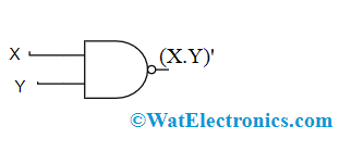
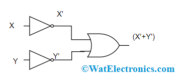
(X.Y)’ = X’ + Y’
It can also be stated as NAND = Bubbled OR
The theorem can be verified using a truth table and logical gates
Truth Table:
| Input Variables | Output Terms | |||||
| X | Y | X.Y | (X.Y)’ | X’ | Y’ | X’+Y’ |
| 0 | 0 | 0 | 1 | 1 | 1 | 1 |
| 1 | 0 | 0 | 1 | 0 | 1 | 1 |
| 0 | 1 | 0 | 1 | 1 | 0 | 1 |
| 1 | 1 | 1 | 0 | 0 | 0 | 0 |
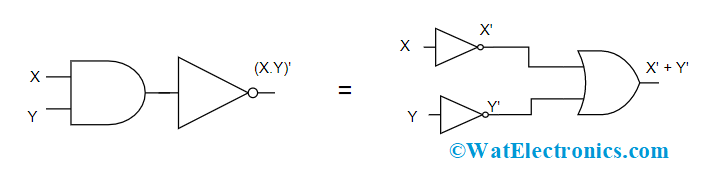
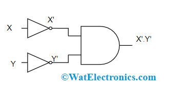
Logic Gates of DeMorgan’s First Law
In the above diagram, the first logic gate arrangement (X.Y)’ is implemented by a NAND gate and the second logic gate arrangement is initially inverts both the inputs, and the inverted results are provided as input to the OR gate. So, the final output is X’ + Y’
Therefore, it is observed that the NAND gate function is equal to the OR gate function having both the inputs as inverted.
DeMorgan’s Second Theorem
The second theorem of DeMorgan’s law defines that the inverted result from OR operation is the same as the AND operation of a complement of each variable where the result equals NOR operation.
Please refer to this link to know more about DeMorgan’s Theorem MCQs
So, DeMorgan’s second theorem formula is:
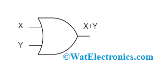
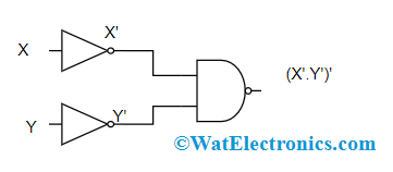
(X+Y)’ = X’.Y’
It can also be stated as NOR = Bubbled AND
The theorem can be verified using a truth table and logical gates
Truth Table:
| Input Variables | Output Terms | |||||
| X | Y | X+Y | (X+Y)’ | X’ | Y’ | X’.Y’ |
| 0 | 0 | 0 | 1 | 1 | 1 | 1 |
| 1 | 0 | 1 | 0 | 0 | 1 | 0 |
| 0 | 1 | 1 | 0 | 1 | 0 | 0 |
| 1 | 1 | 1 | 0 | 0 | 0 | 0 |
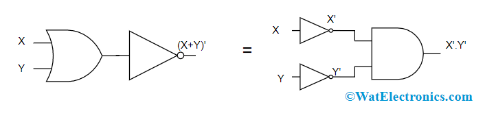
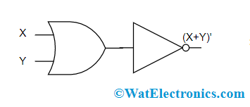
Logic Gates of DeMorgan’s Second Law
In the above diagram, the first logic gate arrangement (X+Y)’ is implemented by a NOR gate and the second logic gate arrangement is initially inverts both the inputs and the inverted results are provided as input to the AND gate. So, the final output is X’. Y’
Therefore, it is observed that the NOR gate function is equal to the AND gate function having both the inputs as inverted.
The same principle can be applied for both 3 and 4 variable inputs where the examples are considered below:
DeMorgan’s theorem formula for 3 variables is
(X.Y.Z)’ = X’+Y’+Z’
And (X+Y+Z)’ = X’.Y’.Z’
DeMorgan’s theorem formula for 4 variables is
(W.X.Y.Z)’ = W’+X’+Y’+Z’
And (W+X+Y+Z)’ =W’.X’.Y’.Z’
Equivalent Gates of DeMorgan’s Theorem
Based on DeMorgan’s first and second theorems, it is observed that all the AND operators in a logical expression can be replaced with OR operators and vice versa and then inverts every term in the expression which means logic ‘0’ to logic ‘1’ and logic ‘1’ to logic ‘0’.
So, to get DeMorgan’s equivalent gates for AND, OR, and NOT gates, inverters are to be added for all the inputs and outputs and alter AND to OR gate and OR to AND gate.
The equivalent gates of DeMorgan’s laws are shown below by comparing with fundamental logical gates.
| Fundamental Logic Gates | DeMorgan’s Logic Gates |
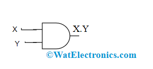 AND Gate |
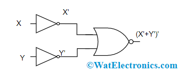 Negative NOR Gate |
 NAND Gate |
 Negative OR Gate |
 OR gate |
 Negative NAND Gate in DeMorgan’s Theorem |
 NOR gate |
 Negative AND Gate in DeMorgan’s Theorem |
Proof of DeMorgan’s Laws
This section explains on proving DeMorgan’s theorems using a truth table. For this let us consider three variables as inputs.
- (X+Y+Z)’ = X’.Y’.Z’
| X | Y | Z | X’ | Y’ | Z’ | (X+Y+Z) | (X+Y+Z)’= LHS | X’Y’Z’ = RHS |
| 0 | 0 | 0 | 1 | 1 | 1 | 0 | 1 | 1 |
| 0 | 0 | 1 | 1 | 1 | 0 | 1 | 0 | 0 |
| 0 | 1 | 0 | 1 | 0 | 1 | 1 | 0 | 0 |
| 0 | 1 | 1 | 1 | 0 | 0 | 1 | 0 | 0 |
| 1 | 0 | 0 | 0 | 1 | 1 | 1 | 0 | 0 |
| 1 | 0 | 1 | 0 | 1 | 0 | 1 | 0 | 0 |
| 1 | 1 | 0 | 0 | 0 | 1 | 1 | 0 | 0 |
| 1 | 1 | 1 | 0 | 0 | 0 | 1 | 0 | 0 |
- (X.Y.Z)’ = X’+Y’+Z’
| X | Y | Z | X’ | Y’ | Z’ | (X.Y.Z) | (X.Y.Z)’= LHS | X’+Y+’Z’ = RHS |
| 0 | 0 | 0 | 1 | 1 | 1 | 0 | 1 | 1 |
| 0 | 0 | 1 | 1 | 1 | 0 | 0 | 1 | 1 |
| 0 | 1 | 0 | 1 | 0 | 1 | 0 | 1 | 1 |
| 0 | 1 | 1 | 1 | 0 | 0 | 0 | 1 | 1 |
| 1 | 0 | 0 | 0 | 1 | 1 | 0 | 1 | 1 |
| 1 | 0 | 1 | 0 | 1 | 0 | 0 | 1 | 1 |
| 1 | 1 | 0 | 0 | 0 | 1 | 0 | 1 | 1 |
| 1 | 1 | 1 | 0 | 0 | 0 | 1 | 0 | 0 |
Example
This section gives an example on intersection using DeMorgan’s law
Consider
X = {a, b, c, d, e} and Y = {a, b, v} and Z = {b, v, e}
Using DeMorgan’s second law, we know that
(X ꓵ Y)C = XC ꓴ YC
Here, (Y ꓵ Z) = {a, b, v} ꓵ {b, v, e}
(Y ꓵ Z) = {b, v}
(Y ꓵ Z)’ = {a, c, e} = LHS
Now, Y = {a, b, v} and Y’ = {c,a}
Z = {b, v, e} and Z’ = {a, b}
Y’ ꓴ Z’ = {c,a} ꓴ {a, e}
Y’ ꓴ Z’ = {a, c, e} = RHS
So, LHS = RHS
Applications
The applications of DeMorgan’s theorem are crucially observed in multiple domains of engineering and mathematics.
- In the domain of engineering, using DeMorgan’s laws, boolean expressions can be built easily only through one gate which is usually NAND or NOR gates. This results in hardware design at a cheaper cost.
- Used in the verification of SAS code.
- Implemented in computer and electrical engineering domain.
- DeMorgan’s laws are also employed in Java programming.
Limitations
The limitation of DeMorgan’s laws is the relation of conjunction and inclusive dis-junction happens through negation.
1). What is the purpose of De Morgan’s Law?
The main usage of DeMorgan’s law is in designing digital circuits. These laws relate to the union and intersection of sets using complements. It explains that the complement of the sum of all input variables equals the product of the complement of every term.
2). What is De Morgan’s Law in statistics?
In the domain of statistics, it also needs set theory. The statements from the DeMorgan theorem define interactions between several set theory functions. The laws are
(X ꓵ Y)C = XC ꓴ YC and
(X ꓴ Y)C = XC ꓵ YC
3). What is the use of DeMorgan’s Theorem?
The use of DeMorgan’s theorem is that a NOR gate equals to AND gate with complemented inputs. Also, NAND gate equals to OR gate with complemented inputs
4). What is bubbled AND gate?
Bubbled AND gate is an AND gate having inverted inputs. This is also termed as negative AND gate.
This is all about DeMorgan’s Theorem. Through these laws, the evaluation and simplification of the logical expression can be done in an easier approach. This article has provided detailed information on DeMorgan’s theorem statement, its first and second laws, proof using truth tables and equivalent gates. Know more on what are the various examples of DeMorgan’s theorem?