Modulation is an extremely important process in communication technology. It allows signals to transmit information from one point to another by means of a communication channel. We can send a signal over a particular frequency range by using different types of modulation techniques. PAM is a type of modulation technique that is being effectively used in signal transmission. PAM is basically a type of amplitude modulation where the message is transmitted as a series of pulses where each pulse represents the amplitude of the wave. The modulation is mainly done at the receiver’s end. We use PAM for different purposes. It is a simple modulation technique.
What is Pulse Amplitude Modulation?
Definition: PAM is a type of pulse modulation technique in which the signal to be transmitted is sampled after certain intervals of time. The samples are then made proportional to the modulating signal’s amplitude. If we perform analog modulation, then the pulses generated will be infinite. We perform PAM mostly while transmitting digital data. PAM is used extensively in Ethernet communication.
Pulse Amplitude Modulation Theory
PAM is quite similar to continuous-wave modulation. However, in the case of PAM, the carrier signal takes the form of rectangular pulses while in the case of continuous-wave modulation, the signals are continuous in nature. All these techniques are nothing but types of modulation. In modulation, we add information to the carrier signal. The carrier signal is basically a steady wave that has constant frequency and amplitude. Here we have mentioned the different types of modulation:
Modulation is basically of two types:
- Continuous-wave modulation
- Pulse modulation
Continuous-wave Modulation
A continuous-wave is a type of wave which has a fixed frequency and amplitude. In continuous-wave modulation, continuous signals are formed after modulation. This type of modulation requires very less bandwidth and the analog signal can be used. We use a high-frequency sine wave for the carrier.
There are three types of continuous-wave modulation:
- Amplitude Modulation
- Frequency Modulation
- Phase modulation
Pulse Modulation
In pulse modulation, the signal to be transmitted is in the formation of pulses. It is of two types which are Analog Pulse Modulation and Digital Pulse Modulation. Analog Pulse Modulation is of three types which are PAM, PWM, and PPM.
Digital modulation is of two types:
- Pulse Code Modulation
- Delta modulation
PAM
PAM is a type of analog modulation technique. It is the type of modulation in which we sample the signals at each interval and we make sure that the samples are directly proportional to the signal’s amplitude at that particular instance. Sometimes, the samples can also be inversely proportional to the signal’s amplitude Basically, the transition of data can be brought about by varying the amplitude.
Sampling techniques are of two types which can be used to transmit a signal using PAM. They are:
- Flat Top PAM
- Natural PAM
Flat Top PAM
Flat top PAM is a sampling technique. In the case of Flat-Top pulse-amplitude modulation, the amplitude of each pulse is made directly proportional to the amplitude of the modulating signal during the time of occurrence of the pulses. This is basically done to remove noise. The top of the amplitude of the signal will remain flat.
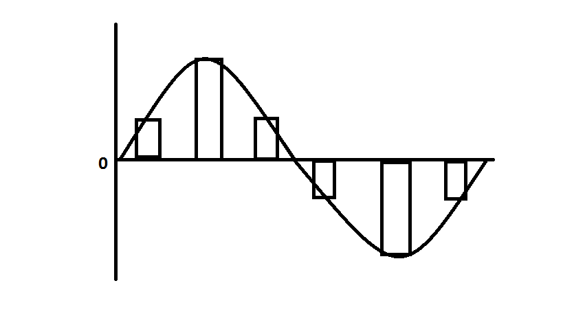
Flat Top Pulse Amplitude Modulation
Natural PAM
In natural PAM, the amplitude of the pulse is made directly proportional to the amplitude of the modulating signal during the time of pulse occurrence. The top of the amplitude of the signal will retain the original shape of the wave.
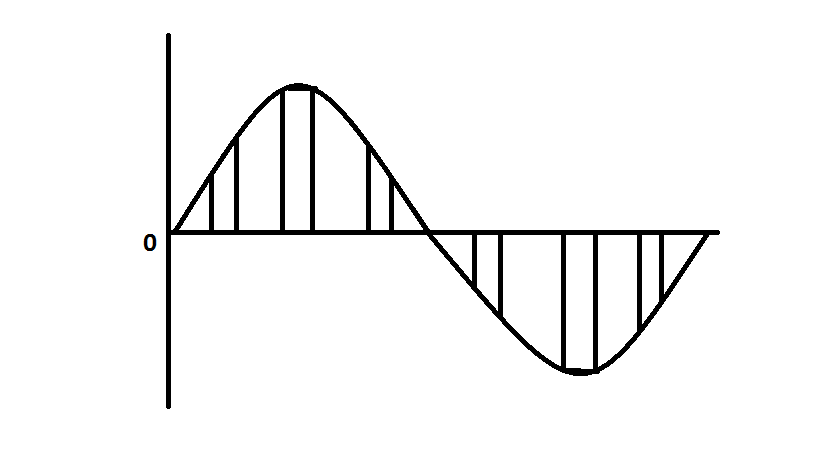
Natural Pulse Amplitude Modulation
Circuit Diagram of PAM
The circuit diagram consists of a square wave generator. The sine wave which is generated by the sine wave generator is basically based on the Wein Bridge Oscillator circuit.
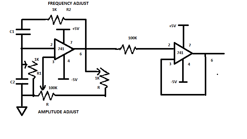
Circuit Diagram of Pulse Amplitude Modulation
Both the frequency and amplitude of the oscillator can be adjusted by using a potentiometer. We can vary the key of R2 (potentiometer) and we can adjust the amplitude by using R1(potentiometer). The frequency of the wave which is generated is given by the formula F = 1/(2π√R1R2C1C2).
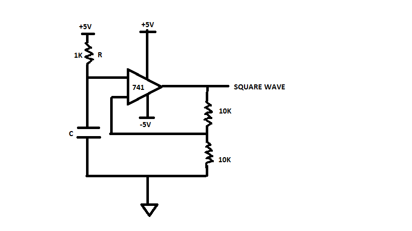
Op-Amp Circuit
The square wave is basically generated using the op-amp amplifier. We can use the op-amp to reduce the complexity of the generating sine wave.
PAM is of two types:
- Single Polarity Pam
- Double Polarity PAM
In Single Polarity PAM, we add a fixed direct current to the pulses so that all the pulses are made positive. We add a fixed DC bias to the signal. In the case of Double Polarity PAM, the pulses can be both negative as well as positive.
Demodulation of Pulse Amplitude Modulation
During the demodulation process, the PAM signal to a low pass filter. This low pass filter is used to eliminate the high-frequency ripples. This, in turn, generates the modulated signal which is then passed to the inverter amplifier which is used to amplify the signal so that the demodulated wave has almost the same amplitude as that of the modulating signal.
Applications of Pulse Amplitude Modulation
- We can use them in Ethernet communication signals
- PAM signals can be used in photo-biology
- We can use PAM signal as an electronic driver for LED lighting
Advantages of Pulse Amplitude Modulation
- The process is simple for both modulation as well as demodulation technique
- We can generate other modulating signals as well.
- It can be implemented quite easily.
Disadvantages of PAM
- We should use a very large bandwidth for transmission purpose
- A lot of noise will be generated
- The signals can vary and so a lot of power will be required during transmission.
FAQs
1). Why is pulse amplitude modulation used?
PAM is used to modulate the signal wave during the transmission of data. PAM is a type of analog to digital conversion technique.
2). What is pulse amplitude measured in?
The pulse amplitude can be a measure of the current level, voltage level, power level or field intensity.
3). How are pulses graded?
The pulses are graded based on their rate of transmission. We can also grade them based on the amount of distortion.
4). What is pulse processing?
Pulse processing is a transient change in the amplitude of the signal from a baseline value.
5). Is pulse signal analog or digital?
PAM is a type of analog to digital conversion technique where the analog signal is converted to a digital signal.
Please refer to this link to know more about Pulse Code Modulation MCQs, Phase Modulation MCQs, Sample Theory Pulse Modulation MCQs
Thus, this is all about an overview of pulse amplitude modulation. We can see that PAM is a very important modulating technique which has various application. It can be used extensively in electronics and telecommunication systems for various important purposes.