Transistors are the basic building blocks of modern electronic devices. So there are numerous transistors available. Among them, the MMBT3906 transistor stands out because of its efficiency and versatility. The main function of this PNP BJT is to provide a higher surge current ability with less power loss. So this PNP transistor is the perfect choice for automated installation due to its high efficiency. This article explores the MMBT3906 transistor pin configuration, features, specifications, and applications.
What is MMBT3906 Transistor?
MMBT3906 is a PNP-type switching transistor that comes in an SMD (Surface-Mounted Device) SOT-23 plastic package. This transistor provides a higher surge current ability with less power loss. So this transistor is mainly designed for use in general-purpose switches & amplifiers. This transistor has high efficiency, so ideal for automated installation. The collector-to-base or VCBO of this transistor is -40V, the collector-to-emitter voltage or VCEO is -40V, and the emitter-to-base or VEBO is -5V.
MMBT3906 transistor provides an MSL-1 (Moisture Sensitivity Level) according to the J-STD-020 standards & this transistor is halogen-free based on the IEC 61249-2-21 standards. This transistor power dissipation or PD is 350mW & its collector current is -200mAmps. This is most suitable for use in lighting applications, adapters, onboard DC/DC converters, and SMPS (switching mode power supplies).
While looking for a suitable transistor for your application based on a few factors, it is very important to look into a few points on How to Select a Transistor.
Working
The working of the MMBT3906 transistor is, whenever a small amount of current supplies from the emitter terminal to the base then it allows a higher current to supply from the emitter terminal to the collector terminal. So this current amplification property is used in amplification and switching circuits. Whenever the base terminal of this transistor is pulled low then it allows current supply from the emitter terminal to the collector to efficiently turn ON the transistor. On the other hand, whenever the base terminal is at a higher voltage, then the transistor will be turned OFF to avoid current supply from the emitter terminal to the collector.
Pin Configuration:
The MMBT3906 transistor pin configuration is shown below which includes three terminals like the following.
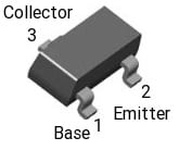
MMBT3906 Transistor Pin Configuration
- Pin-1 (Base): This terminal is used to bias the transistor.
- Pin-2 (Emitter): This terminal function is to supply charger carriers toward the base terminal.
- Pin-3 (Collector): This terminal collects the majority of charge carriers, emitted from the emitter.
Features & Specifications:
The features and specifications of the MMBT3906 transistor include the following.
- Transistor polarity is PNP.
- It includes three terminals.
- Configuration is single.
- The mounting style is SMD or SMT.
- The package or case is SOT-23-3
- DC Current gain or hfe ranges from 100 to 300.
- Its transition frequency is 250 MHz.
- Its noise figure is 4 dB.
- Collector to emitter voltage or VCEO is 40 V
- Collector to base voltage or VCBO is 40 V.
- The emitter to base voltage or VEBO is 6 V.
- The saturation voltage from collector to emitter is 400 mV.
- DC collector’s current maximum is 200 mA.
- Its power dissipation is 350 mW.
- The gain BW product is 250 MHz.
- Operating temperature ranges from -55°C to +150°C.
Equivalent and Complementary Transistors
Equivalent & replacement MMBT3906 transistors are; 2SA1366, 2SA1519, 2SA1518, 2SA1520, 2SA1521, BC807, 2SB710A, BCW68, BCX17, FMMT2907A, FMMT2907, FMMT2907AR, FMMT3906, FMMT2907R, FMMT591, FMMTA55, FMMT591Q, FMMTA56, KN2907S, KN2907AS, KN3906S, KST3906, KST2907A, KST4403, KST56, KST55, KTN2907AS, MMBT200, KTN2907S, MMBT2907, MMBT3906L, MMBT2907A, MMBT3906LT1, MMBT3906LT3, MMBT3906LT1G, MMBT3906LT3G, MMBT4355, MMBT4354, MMBT4403, MMBTA56, MMBTA55, PMBT2907, PMBT3906, PMBT2907A, PMBT4403, PMST2907, PMBTA56, PMST2907A, SMBTA56 or SMBTA55. The complementary MMBT3906 transistor is the NPN MMBT3904 transistor.
Replacing a suitable transistor in any circuit based on requirement is very important. To know how to replace it, please refer to this; Replacing Transistors in Electronic Circuits: Factors and Considerations.
Discrete Driver Circuit with MMBT3906 Transistor
The discrete driver circuit is shown below which is very useful in controlling Q2 transistor conduction within a synchronous flyback. So this circuit provides you controlled turn-on gate current and defends the rectifier gate from higher reverse voltage.
This circuit begins with a negative (-Ve) voltage on the transformer’s outputs. The 12Volts output is negative more than the 5V output which causes the Q1 transistor to conduct & short the voltage from gate-to-source terminals on the Q2 power FET by turning it off rapidly. When the base current is supplied throughout the R2 resistor, then there will be a negative voltage on the C1 capacitor.
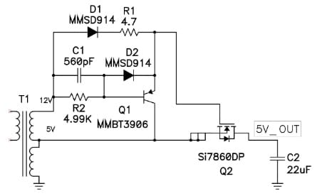
Discrete Driver Circuit with MMBT3906 Transistor
At this moment, the main FET conducts & stores energy within the transformer’s magnetizing inductance. Once this main FET turns off the output voltage of the transformer swings positive. So, the gate-to-source of the Q2 transistor is forward-biased fast through R1 & D1 which causes the Q2 transistor to conduct. So the base-to-emitter junction of Q1 is protected through D2 whenever the C1 capacitor discharges.
This circuit will stay in this condition until the main FET is again turned on. So, the o/p current can discharge the o/p capacitors actually as a synchronous buck might perform. Turning ON the main FET fails the voltage supply on the secondary transformer & eliminates the positive drive from the Q2 transistor. So this transition results in an important shoot throughout from overlapping the primary FET & Q2 conduction time. To reduce the time whenever both primary & secondary FETs are turned ON then Q1 shorts the gate terminal to-source on the Q2 synchronous rectifier as quickly as possible.
Please refer to this link for the MMBT3906 Transistor Datasheet.
Advantages & Disadvantages
The advantages of the MMBT3906 transistor include the following.
- MMBT3906 transistor is a small signal PNP transistor.
- It has many benefits like; high gain, low saturation voltage, and high reliability.
- It has epitaxial planar die design.
- It is completely Lead-Free & RoHS Compliant.
- This transistor is perfect for medium power switching & amplification.
- It has a surface mount package.
The disadvantages of the MMBT3906 transistor include the following.
- Transistors particularly in high-performance applications consume a huge power, so it can lead to the generation of heat & reduced energy efficiency.
- Transistors are small in size, thus they can face technological and physical limitations that make additional miniaturization challenging.
- The possibility of current leakage can lead to data errors within electronic circuits.
- The transistor fabrication at the nanoscale level needs highly expensive and complex manufacturing developments.
- These can be vulnerable to a variety of reliability issues like electromigration, dielectric breakdown, and hot carrier effects which can limit their performance and lifetime over time.
- These can be simply affected by electromagnetic interference & other noise sources that corrupt the signal performance & quality within electronic circuits.
Connecting a base resistor to the base terminal of the transistor is mandatory to avoid it being damaged. So, Please refer to this link for; Choosing Base Resistance for Transistors in Electronic Circuits.
Applications
The applications of the MMBT3906 transistor include the following.
- MMBT3906 transistor is used for general-purpose switching & amplification purposes.
- This transistor is used in lighting applications, adapters, switching mode power supplies, and onboard DC/DC converters.
- This type of transistor is used in a wide range of applications due to its versatility.
- It is used in switching circuits because its high switching speed is beneficial in digital circuits which require fast on/off states.
- This transistor is used within low-power audio amplifiers & signal amplification circuits because of its high transition frequency.
- It works very well for signal processing in a variety of electronic devices.
- It maintains stable output voltage as part of a feedback loop within voltage regulator circuits.
- This transistor is very common in TVs, radios & other household electronic devices that need consistent switching & amplification.
- This transistor is mainly designed to attain high surge current & low power loss capability.
- It is used for analog and digital circuits amplification and also in high-precision applications like data conversion & analog signal processing.
- It is a significant component in DC to DC.
- It is used in digital circuits to achieve high performance within different components like; barrier logic, counters & frequency dividers.
- It is used in industrial control systems to ensure efficient and stable system operation.
Thus, this is an overview of the MMBT3906 Transistor, pinout, specifications, circuit, working, and its applications. This transistor comes in an SMD (Surface-Mounted Device) SOT-23 plastic package and is designed mainly to be used in general-purpose switches & amplifiers to amplify and switch electronic signals as well as electrical power. Here is a question for you, what is the MMBT3904 transistor?