At present, semiconductor technology is developing very quickly, so the power utilization & the size of various types of radars have been reduced greatly. So, the function of radar is also getting stronger by using ultra-wideband technology, millimeter-wave, multiple transmission & receptions by increasing computing capacities. These sensors are used every day for different purposes in different applications like weather forecast weekly, onboard vehicle systems & controlling traffic. In recent days, radar sensors have been utilized for smart buildings, autonomous cars, wearable devices, and many more. So, this article gives brief information on a radar sensor – working with applications.
What is Radar Sensor?
A radar sensor definition is; a conversion device that is used to change the signals from microwave to electrical. The term radar stands for “Radio Detection and Ranging” which is used to detect motion by discovering the position of the object, characteristics of motion, shape & path of motion, tracking, contactless detection, one or more objects positioning through electromagnetic waves in the microwave Gigahertz (GHz) range. These sensors cannot be affected by darkness and light but they are capable of detecting obstructions like glass. As compared to ultrasound, radars detect longer distances & it is very secure for people & animals.
Radar sensor range mainly depends on the technical development of the sensor. For a small radar sensor including an extremely narrow beam cone, the measurement range is up to 60 meters. So, the coverage range for commercial applications generally varies from 1cm to a few 100meters. The radar sensor’s electromagnetic waves penetrate different materials.
Radar Sensor Block Diagram
The block diagram of the pulse radar sensor is shown below. This radar sensor includes different functional blocks where each block and its function are discussed below.
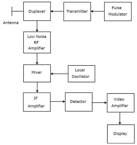
Radar Block Diagram
Pulse Modulator
The pulse modulator generates a pulse-modulated signal as an output & this output signal is given to the Transmitter.
Transmitter
The transmitter transmits a pulse-modulated signal to the duplexer received by the pulse modulator.
Duplexer
The duplexer is a microwave switch that connects the Antenna to both the Tx section & Rx section alternately. Once this switch connects the antenna to the Tx, then the antenna generates the pulse-modulated signal, Likewise, the signal received by Antenna is provided to Low Noise RF Amplifier once the Antenna is connected by the switch to the Low Noise RF Amplifier.
Low Noise RF Amplifier
The low noise RF amplifier amplifies the RF weak signal which is obtained by Antenna. So, this amplifier’s output is simply connected to the Mixer.
Local Oscillator
The local oscillator generates a signal that has a stable frequency. So, the o/p of this oscillator is simply given to Mixer.
Mixer
The mixer provides both sum & difference of the frequencies that are applied to it. The difference in the frequencies is the IF (Intermediate Frequency) type. This intermediate frequency is given to the IF amplifier.
IF Amplifier
This amplifier function is to amplify the IF signal which is attained from Mixer. It develops the Signal to Noise (S/N) Ratio at the output.
Detector
The detector demodulates the signal obtained from the IF amplifier.
Video Amplifier
A video amplifier is used to amplify the video signal, which is attained at the detector’s output.
Display
Generally, the display is used to display the amplified video signal on the display of CRT.
Radar Sensor Working Principle
The working principle of the RADAR sensor is to detect & locate different objects by radiating radio signals from the sensor into space. Some of these radio signals will be interrupted by hitting the targets and they are reflected back in various directions. Some of them are directed back to the radar where they are obtained & amplified. By using signal processing, the decision is taken to check whether an echo signal of the target has been detected or not. The location of the target & other data can be obtained from the echo signal
Radar Sensor Types
These are two types of radars available depending on the signal type by which Radar can function like pulse radar and CWR (continuous wave radar). So, let us discuss these two Radars.
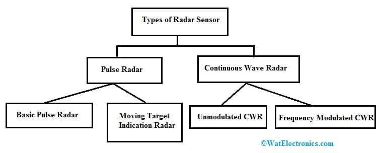
Types of Radar Sensor
Pulse Radar
The pulse radar can be defined as; the radar which works by the pulse signal. These types of radars are classified into two types depending on the target type it detects like basic pulse radar and moving target indication radar.
Basic Pulse Radar
This Radar works with pulse signals to detect stationary targets. This radar utilizes an Antenna to transmit & receive signals using Duplexer. At every clock pulse, the antenna transmits a pulse signal. The time duration among the two clock pulses must be selected in such a way that the echo signal related to the current clock pulse must be obtained before the next clock signal.
Moving Target Indication Radar
The moving target indication radar can be defined as; a radar that works with pulse signal to detect non-stationary targets. This radar is also known as MTI Radar. This radar uses an antenna to transmit & receive signals using Duplexer. This kind of pulse radar also uses the Doppler effect principle to differentiate the non-stationary targets from motionless objects.
Continuous Wave Radar
This continuous wave radar simply works through continuous waves or signals. This radar uses Doppler Effect to detect non-stationary objects. These radars are classified into two types unmodulated CWR or frequency modulated CWR.
Unmodulated CWR
This unmodulated continuous wave radar works with a continuous signal to detect non-stationary targets. This kind of radar is also known as continuous wave doppler radar. This kind of radar needs two Antennas where one Antenna is mainly used to transmit the signal & remaining Antenna is used to get the signal. So, it is used to measure the target speed only but not the object’s distance from the Radar.
Frequency Modulated CWR
The continuous wave radar which used the FM or frequency modulation then it is called frequency modulated continuous wave radar or FMCW. This type of CWR is also known as FMCW doppler radar or CWFM radar (Continuous Wave Frequency Modulated Radar).
This type of radar uses two Antennas where one antenna is used for transmitting the signal & another one is used for obtaining the signal. So, it measures not only the target speed and also the target distance from the Radar.
Difference b/w Radar Sensor Vs Ultrasonic Sensor
The difference b/w radar sensor Vs ultrasonic sensors include the following.
|
Radar Sensor |
Ultrasonic Sensor |
| The sensor used to convert the signals from microwave echo to electrical is known as a radar sensor. | The sensor which is used to measure the main distance to a target through ultrasonic sound waves is known as an ultrasonic sensor. |
| This sensor uses electromagnetic waves to work. | This sensor generates sound waves to work. |
| The traveling speed of radar signals is high. | The traveling speed of ultrasonic signals is low. |
| The waves from this sensor will reflect the object and move very fast at a known speed. | The sound waves travel at sound speed to reflect the object & come back to the sensor. |
| This sensor’s electromagnetic waves respond in a different way to specific materials. | This sensor’s sound waves will not respond to specific materials.
|
| This sensor will be affected by several variables. | This sensor will be affected by temperature. |
| This sensor is applicable to gas and oil, paper and pulp, pharmaceuticals, clarifiers, plastic pellets, granular solids, etc. | This sensor is applicable in measuring the liquid flow, open-channel flow, solids level, presence detection & object profiling. |
Radar Sensor Arduino
The radar sensor interfacing with a microcontroller like Arduino is shown below. The main intention of this project is to design a radar system prototype with an Arduino board to detect stationary & moving objects.
The required components to make this project mainly include an Arduino UNO board, HC-SR04 Ultrasonic Sensor, servo motor, and connecting wires.
HCSR04 Ultrasonic Sensor
The HCSR04 ultrasonic sensor is mainly used for measuring the object’s distance by simply transmitting ultrasonic signals & changes the reflected signals into an electrical signal. This sensor mainly includes two components like the transmitter & receiver. The transmitter of this sensor generates the sound signals with a piezoelectric crystal whereas the receiver meets the sound once it has moved to & from the object.
To calculate the distance of the object, this sensor simply measures the time used by the signal to move in between the transmitter and the receiver.
The distance calculation can be done by using this formula D = ½ T x C
Where,
‘D’ is distance, ‘T’ is time and ‘C’ is the sound speed which is 343 m/sec.
Pin Configuration
The pin configuration of the HCSR04 ultrasonic sensor is shown below. This sensor includes four pins and each pin & its function are discussed below.
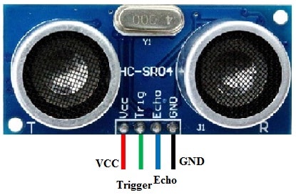
HCST04 Pin Configuration
- Pin1 (Vcc): This is the Vcc pin used to power the ultrasonic sensor with +5V.
- Pin2 (Trigger): This is an i/p pin, used to transmit the ultrasound signal from the transmitter of the sensor.
- Pin3 (Echo): This is an o/p pin that goes high for a certain time period which will be equivalent to the time used for the ultrasound signal to go back to the sensor.
- Pin4 (Ground): This is a Ground pin.
Features & Specifications
The features and specifications of radar sensors include the following.
- The operating voltage of this sensor is +5V.
- Measuring distance theoretically ranges from 2cm – 450cm.
- Measuring distance practically ranges from 2cm – 80cm.
- Its accuracy is 3mm.
- The covered measuring angle is less than 15°.
- The operating current is less than 15mA.
- The operating frequency is 40Hz.
- Dimension is 45 x 20 x 15mm.
Servo Motor
A simple DC motor like a servo motor is used to control a particular angular revolution using extra servomechanism. The Servo motor simply rotates based on our requirement and after that, it stops. This motor utilizes positional feedback for controlling the position & speed. Unlike a typical electric motor, this motor starts & stops based on the input of power.
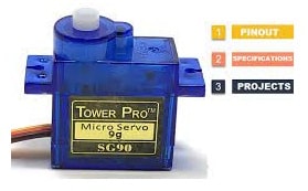
Servo Motor
Connections
To fix the ultrasonic sensor, a mounting bracket is used. So this is optional, you can also use cardboard for mounting this sensor with a servo motor. The following image shows the connections of the ultrasonic sensor & servo motor using an Arduino Uno. These connections are extremely simple.
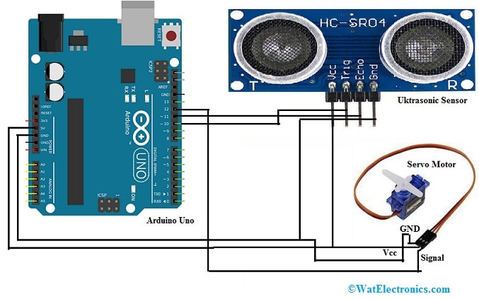
Radar Sensor Interfacing with Arduino
- The VCC pin of Arduino Uno is connected to the VCC pins of both the ultrasonic sensor and servo motor.
- The GND pin of Arduino Uno is connected to the GND pins of both the ultrasonic sensor and servo motor.
- The D10 pin of Arduino Uno is connected to the Trig pins of the ultrasonic sensor.
- The D11 pin of Arduino Uno is connected to the Echo pins of the ultrasonic sensor.
- The D12 pin of Arduino Uno is connected to the signal pin of the motor.
Arduino Code
We need to download two codes from Arduino IDE 1.8.13 & Processing IDE to complete this Arduino radar project. This project uses two codes one is Arduino UNO & the remaining code is for Processing.
Arduino Source Code
The Arduino source code for the Arduino radar project is shown below.
// Includes the Servo library
#include <Servo.h>.
// Defines Tirg and Echo pins of the Ultrasonic Sensor
const int trigPin = 10;
const int echoPin = 11;
// Variables for the duration and the distance
long duration;
int distance;
Servo myServo; // Creates a servo object for controlling the servo motor
void setup() {
pinMode(trigPin, OUTPUT); // Sets the trigPin as an Output
pinMode(echoPin, INPUT); // Sets the echoPin as an Input
Serial.begin(9600);
myServo.attach(12); // Defines on which pin is the servo motor attached
}
void loop() {
// rotates the servo motor from 15 to 165 degrees
for(int i=15;i<=165;i++){
myServo.write(i);
delay(30);
distance = calculateDistance();// Calls a function for calculating the distance measured by the Ultrasonic sensor for each degree
Serial.print(i); // Sends the current degree into the Serial Port
Serial.print(“,”); // Sends addition character right next to the previous value needed later in the Processing IDE for indexing
Serial.print(distance); // Sends the distance value into the Serial Port
Serial.print(“.”); // Sends addition character right next to the previous value needed later in the Processing IDE for indexing
}
// Repeats the previous lines from 165 to 15 degrees
for(int i=165;i>15;i–){
myServo.write(i);
delay(30);
distance = calculateDistance();
Serial.print(i);
Serial.print(“,”);
Serial.print(distance);
Serial.print(“.”);
}
}
// Function for calculating the distance measured by the Ultrasonic sensor
int calculateDistance(){
digitalWrite(trigPin, LOW);
delayMicroseconds(2);
// Sets the trigPin on HIGH state for 10 micro seconds
digitalWrite(trigPin, HIGH);
delayMicroseconds(10);
digitalWrite(trigPin, LOW);
duration = pulseIn(echoPin, HIGH); // Reads the echoPin, returns the sound wave travel time in microseconds
distance= duration*0.034/2;
return distance;
}
Here is the processing code for the Arduino radar project:
Processing Code:
The processing code for the Arduino radar project is shown below.
import processing.serial.*; // imports library for serial communication
import java.awt.event.KeyEvent; // imports library for reading the data from the serial port
import java.io.IOException;
Serial myPort; // defines Object Serial
// defubes variables
String angle=””;
String distance=””;
String data=””;
String noObject;
float pixsDistance;
int iAngle, iDistance;
int index1=0;
int index2=0;
PFont orcFont;
void setup() {
size (1200, 700); // ***CHANGE THIS TO YOUR SCREEN RESOLUTION***
smooth();
myPort = new Serial(this,”COM5″, 9600); // starts the serial communication
myPort.bufferUntil(‘.’); // reads the data from the serial port up to the character ‘.’. So actually it reads this: angle,distance.
}
void draw() {
fill(98,245,31);
// simulating motion blur and slow fade of the moving line
noStroke();
fill(0,4);
rect(0, 0, width, height-height*0.065);
fill(98,245,31); // green color
// calls the functions for drawing the radar
drawRadar();
drawLine();
drawObject();
drawText();
}
void serialEvent (Serial myPort) { // starts reading data from the Serial Port
// reads the data from the Serial Port up to the character ‘.’ and puts it into the String variable “data”.
data = myPort.readStringUntil(‘.’);
data = data.substring(0,data.length()-1);
index1 = data.indexOf(“,”); // find the character ‘,’ and puts it into the variable “index1”
angle= data.substring(0, index1); // read the data from position “0” to the position of the variable index1 or that’s the value of the angle the Arduino Board sent into the Serial Port
distance= data.substring(index1+1, data.length()); // read the data from position “index1” to the end of the data pr that the value of the distance
// converts the String variables into Integer
iAngle = int(angle);
iDistance = int(distance);
}
void drawRadar() {
pushMatrix();
translate(width/2,height-height*0.074); // moves the starting coordinats to new location
noFill();
strokeWeight(2);
stroke(98,245,31);
// draws the arc lines
arc(0,0,(width-width*0.0625),(width-width*0.0625),PI,TWO_PI);
arc(0,0,(width-width*0.27),(width-width*0.27),PI,TWO_PI);
arc(0,0,(width-width*0.479),(width-width*0.479),PI,TWO_PI);
arc(0,0,(width-width*0.687),(width-width*0.687),PI,TWO_PI);
// draws the angle lines
line(-width/2,0,width/2,0);
line(0,0,(-width/2)*cos(radians(30)),(-width/2)*sin(radians(30)));
line(0,0,(-width/2)*cos(radians(60)),(-width/2)*sin(radians(60)));
line(0,0,(-width/2)*cos(radians(90)),(-width/2)*sin(radians(90)));
line(0,0,(-width/2)*cos(radians(120)),(-width/2)*sin(radians(120)));
line(0,0,(-width/2)*cos(radians(150)),(-width/2)*sin(radians(150)));
line((-width/2)*cos(radians(30)),0,width/2,0);
popMatrix();
}
void drawObject() {
pushMatrix();
translate(width/2,height-height*0.074); // moves the starting coordinats to new location
strokeWeight(9);
stroke(255,10,10); // red color
pixsDistance = iDistance*((height-height*0.1666)*0.025); // covers the distance from the sensor from cm to pixels
// limiting the range to 40 cms
if(iDistance<40){
// draws the object according to the angle and the distance
line(pixsDistance*cos(radians(iAngle)),-pixsDistance*sin(radians(iAngle)),(width-width*0.505)*cos(radians(iAngle)),-(width-width*0.505)*sin(radians(iAngle)));
}
popMatrix();
}
void drawLine() {
pushMatrix();
strokeWeight(9);
stroke(30,250,60);
translate(width/2,height-height*0.074); // moves the starting coordinats to new location
line(0,0,(height-height*0.12)*cos(radians(iAngle)),-(height-height*0.12)*sin(radians(iAngle))); // draws the line according to the angle
popMatrix();
}
void drawText() { // draws the texts on the screen
pushMatrix();
if(iDistance>40) {
noObject = “Out of Range”;
}
else {
noObject = “In Range”;
}
fill(0,0,0);
noStroke();
rect(0, height-height*0.0648, width, height);
fill(98,245,31);
textSize(25);
text(“10cm”,width-width*0.3854,height-height*0.0833);
text(“20cm”,width-width*0.281,height-height*0.0833);
text(“30cm”,width-width*0.177,height-height*0.0833);
text(“40cm”,width-width*0.0729,height-height*0.0833);
textSize(40);
text(“Robu.in”, width-width*0.875, height-height*0.0277);
text(“Angle: ” + iAngle +” °”, width-width*0.48, height-height*0.0277);
text(“Distance: “, width-width*0.26, height-height*0.0277);
if(iDistance<40) {
text(” ” + iDistance +” cm”, width-width*0.225, height-height*0.0277);
}
textSize(25);
fill(98,245,60);
translate((width-width*0.4994)+width/2*cos(radians(30)),(height-height*0.0907)-width/2*sin(radians(30)));
rotate(-radians(-60));
text(“30°”,0,0);
resetMatrix();
translate((width-width*0.503)+width/2*cos(radians(60)),(height-height*0.0888)-width/2*sin(radians(60)));
rotate(-radians(-30));
text(“60°”,0,0);
resetMatrix();
translate((width-width*0.507)+width/2*cos(radians(90)),(height-height*0.0833)-width/2*sin(radians(90)));
rotate(radians(0));
text(“90°”,0,0);
resetMatrix();
translate(width-width*0.513+width/2*cos(radians(120)),(height-height*0.07129)-width/2*sin(radians(120)));
rotate(radians(-30));
text(“120°”,0,0);
resetMatrix();
translate((width-width*0.5104)+width/2*cos(radians(150)),(height-height*0.0574)-width/2*sin(radians(150)));
rotate(radians(-60));
text(“150°”,0,0);
popMatrix();
}
Output
Once the code is uploaded, then the servo motor starts rotating from 0 – 180 degrees & again it rotates back to 0 degrees. Along with this servo motor, an ultrasonic sensor also rotates because it is mounted over the motor. Now you have to open the processing application & paste the processing code. So in this code, you need to update the number of COM ports where your Arduino UNO board is allied. After that, need to run this process code. So, if this code is correct then you will obtain a fresh window which is the graphical data representation from the sensor that is signified within a radar-type display. If this sensor detects any object in its range, then you can monitor the same on the graphical representation.
Advantages
The advantages of radar sensors include the following.
- These sensors work in difficult weather conditions like dust, rain, and fog.
- This sensor is capable of covering close distance & long distance range also.
- One of the main benefits of these sensors as compared to other sensors is their velocity & its motion detection
- The signals emitted from this sensor can easily penetrate different mediums like fog, clouds, snow & mist.
- The radar signals can also penetrate insulators like plastic & rubber because they do not hinder these signals from gathering data.
- It provides the precise position of a target.
- It determines the target velocity.
- The data gathered by RADAR is sufficient to provide information on whether the target was stationary or in motion.
- RADAR uses radio signals to travel within space or air. So they do not need any medium to be transferred.
- RADAR signals can aim at different objects simultaneously.
- It does not depend on wire connectivity because it is wireless.
- These are not expensive particularly if utilized for major projects.
- It stores large amounts of data that can be utilized for the above function.
- The radio signals generated from RADAR cover a large geographical area.
- RADAR systems provide information on target coverage many times.
- Data acquisition is very easy at various scales.
- The data return back by radar systems is very fast if the region in observation is not very wide.
- The data provided by RADAR systems can be utilized by various industries.
- RADAR systems get information from remote areas of the planet like active volcanoes.
Disadvantages of RADAR
The disadvantages of radar sensors include the following.
- The time taken by a radar system to lock on an object is more.
- The beam range of this system is wider above 50ft in diameter.
- The operating range of the radar is shorter like 200ft
- The receiver is saturated by large targets when it is near the Transmitter.
- RADAR can be obstructed by various objects & mediums within the air.
- It cannot differentiate or determine several targets.
- It cannot distinguish the object’s color.
- It cannot determine targets that are deep within the sea.
- RADAR systems cannot provide information regarding the kind of object being resolved.
- These are not extremely accurate.
- These systems are interrupted by additional signals.
- These are not stable and also vulnerable to exterior interferences.
- It needs specialized training to examine the data.
Where is a radar sensor used for/Applications?
The applications of radar sensors include the following.
- These are capable of detecting motion, measuring distance, speed, arrival angle & the direction of movement.
- These sensors are applicable wherever detection of vehicles is necessary like trains, trucks, cars, shipping canals, railroads, toll booths, etc otherwise keep away from a collision whenever equipment is moving like manufacturing, ports, onboard mobile equipment & low-visibility factory environments.
- These sensors are used in different fields like the military, sports, security systems, medical treatment, controlling industries, and automotive electrons. intelligent traffic radar, intelligent lighting, etc.
Can radar detect humans?
Radar cannot detect humans who are walking or motionless across the field of radar. But it can simply detect the motion components that are in the region of radar or away from the radar.
How far can radar detect?
The typical detection ranges of radar are from 100 to 3500 km respectively.
Why radar is used in the military application?
Radar is used in the military for air defense, controlling missiles, ground surveillance, air traffic control in the military, navigation, moving target recognition, compression of pulse, tracking, search & rescue, etc.
Thus, this is an overview of a radar sensor. So without using these sensors, we cannot guess the weather, temperature changes tracking, and smart cars driving. So day by day, this technology is improving continuously to use in an innovative way. Here is a question for you, what is Doppler Effect?