In 1878, Samuel Pierpont Langley, an American astronomer invented a sensitive instrument to detect heat and electromagnetic radiation. This instrument is called a Bolometer which is used to measure the low and medium power of microwave energy. In the 1880s, Langley’s Bolometer was invented for the detection of thermal radiation. It can measure the power of electromagnetic radiation by using heating material and temperature resistive element. The Bolometers are very sensitive, efficient, better energy resolution, and also at room temperature which avoids cooling. It can measure low power in the range of 0.1mW to 10mW and medium power in the range of 10mW to 1W. This article describes the detection of heat or electromagnetic radiation using a Bolometer.
What is Bolometer?
Definition: An instrument that is used to detect and measure the heat or power of incident electromagnetic radiation of microwave or RF energy using temperature resistive sensitive element is called Bolometer. Commonly used Temperature resistive sensitive elements are thermistors and Baretter, whose resistance changes in accordance with the temperature. It can measure the low and medium power of microwave energy.
Bolometer Diagram
The Bolometers are the positive or negative temperature coefficients based on the type of temperature resistive sensing element. The Bolometer diagram will be in the form of a bridge, where, one arm contains a resistor which is temperature dependant and it is for measurement of the power of microwave energy. It uses oscillators and differential amplifiers to balance the bridge circuit when it is unbalanced.
Bolometer Circuit
The Bolometer circuit diagram is shown below.
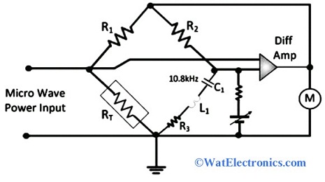
Bolometer Circuit
Two types of temperature-sensitive resistors are used in the Bolometer bridge circuit. They are,
Thermistor: It is made up of semiconductor material with a negative temperature coefficient, whose resistance is inversely proportional to temperature.
Baretter: It is a very thin metal wire with a positive temperature coefficient, whose resistance is directly proportional to the temperature.
Working Principle
The Bolometer working principle is based on the amount of power dissipated on a temperature resistive sensing element. It has a positive or negative temperature coefficient based on the change in resistance. Change in resistance with a change in temperature can be used to detect and measure power or heat of incident electromagnetic radiation or microwave or RF energy. The basic diagram that explains the bolometer working principle is shown below.
Bolometer Working
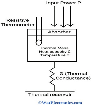
A bolometer contains a thermal reservoir, and a layer of thin metal called absorbing element. The thermal reservoir and absorbing elements are connected through a thermal link. When the electromagnetic radiation is incident on the absorbing element, then it raises the temperature, which is above the thermal reservoir and results in a high temperature greater than the absorbed power. The speed of the instrument is set by the intrinsic thermal time constant that is the same as the absorbing element’s heat capacity and thermal conductance of absorbing element and thermal reservoir. The change in temperature or change in resistance of absorbing elements can be measured by using a thermometer.
Let ‘P’ is the incident power absorbed by the absorber
Heat capacity ‘C’ and temperature ‘T’of thermal mass.
Thermal conductance G is the thermal link that connects the thermal reservoir to a thermal mass.
The increase in temperature is given by,
ΔT = P/G
A temperature dependant resistor called thermometer detects the change in temperature according to the power P. The thermal intrinsic time constant is given by τ = C/G.
Bolometer Working
The device that can measure medium and low power of microwave by using a temperature-sensitive resistor is known as a Bolometer. It measures low power in the range of 0.1mW to 10mW and medium power in the range of 10mW to 1W. A colorimetric method is a heat transfer method that can be used to measure the power of microwave energy. It works on the principle of change in temperature due to the change in resistance of the absorber, measured by thermistor or Baretter. It is a temperature dependant material made up of semiconductor material bead with two leads. As it uses a thermistor or baretter to measure the change in temperature, it could be a positive temperature coefficient (PTC) or a negative temperature coefficient (NTC).
The Bolometer circuit is designed in the form of a bridge circuit. It contains a resistive element that is temperature-sensitive. This element is used to detect and measure the power of given input microwave energy.
When the RF energy or microwave input is applied, the heat produced in the bridge circuit changes the resistance of the temperature resistive element and absorbs the power/radiation, which is to be measured. The change in resistance due to the heat can be measured by the thermistor or baretter.
When a thermistor is used as a resistive element, then the resistance decreases with an increase in temperature. So, Bolometer will be a negative temperature coefficient (NTC).
When baretter is used, then the resistance increases as temperature increases. So, the Bolometer will be a positive temperature coefficient (PTC).
Oscillators and differential amplifiers are used to oscillate the circuit to balance the bridge. Because the bridge becomes unbalanced due to the change in resistance. To balance the bridge circuit, the power will be absorbed by the resistive element.
We can vary and adjust the DC bias to balance the bridge circuit. The applied microwave energy increases the temperature and changes the resistance of the element by absorbing power. Hence this change in resistance could unbalance the bridge circuit.
The imbalance bridge circuit decreases the oscillator output and gets balanced again. Generally, the bridge gets unbalanced due to the cold resistance. The output power increased due to the oscillator and the absorbed power by the resistive element can be measured by using Voltmeter. We can calibrate the change in resistance into power, by checking the three conditions like
- Thermistor load
- Bolometer’s constant load
- Bolometer’s impulse load.
Hence by using Bolometer, minute changes in the resistance can be detected and absorbed power can be easily measured.
Applications
The applications of Bolometer are
- Used to measure the change in resistance
- Used to measure the change in temperature, heat, and radiation.
- Used in thermal cameras
- Used in detectors
- Used in detecting concealed weapons
- Used in scanners to scan fingerprints
- Used in air surveillance
- Used in detecting forest fire
- Used in various astronomical applications.
- Used in detecting electrical responsivity.
Thus, this is all about the power measuring instrument Bolometer-definition, diagram, circuit, working, working principle, and its applications. The attenuators and Bolometers can be combined together to measure power more than 10mW. Here is a question for you, “What advantages and disadvantages of the Bolometers?”