At present, the usage of sensors in mobile devices has increased so it is becoming complex for manufacturers to utilize existing methods like I2C & SPI. So, the MIPI alliance members launched the first I3C protocol which is also called “Improved Inter-Integrated Circuits in the year 2017 by the MIPI Alliance called MIPI I3C v1.0. In October month 2018, the MIPI I3C Basic v1.0 was launched, and after that MIPI I3C v1.1 version was released in the month of December 2019.
This is an evolution of I2C but both the I2C 7 I3C include SDA & SCL lines however, the I2C protocol only supports four-speed modes like 100KHz, 400KHz, 1MHz, and 3MHz) whereas I3C supports speeds up to 12.5MHz within single data rate mode. The throughput bit rate of the I3C protocol is high up to12.5Mbps. So this provides brief information on the I3C protocol and its applications.
What is I3C Protocol?
The I3C is a MIPI standard protocol that is mainly designed to conquer the limitations of I2C protocol like exterior signals required for interrupts, limited speed, and no automatic device detection which is connected to the bus.
The main function of MIPI is to regulate sensor communication, decrease the number of physical pins utilized within the integration of a sensor system, and support some features like high speed and low power which are presently not covered through SPI & I2C. The MIPI I3C Basic specification states that I3C has significant energy consumption and bus speed improvements over I2C.
I3C Protocol Working
The MIPI I3C Bus interface is very helpful in decreasing the number of physical pins utilized within the sensor system & supports high-speed and low-power digital communication which is associated through SPI & UART interfaces so that the I3C protocol will become a single interface to combine different legacy interfaces.
This type of Protocol includes a multi-drop bus at 12.5 MHz and it is 12 times faster as compared to I2C. So, the I3C Protocol interface plays a key role in streamlining sensor integration within smartphones, wearables & IoT devices.
The communication of the I3C protocol can be done in a frame where the frame starts with a START, followed by a minimum of one or above transfers & a STOP. The specification of MIPI i3c will ensure that the format of the CCC command simply follows the rules of SDR protocol. Commands can be addressed to the following:
On the I3C bus, all the devices will use the CCC broadcast command like START, 0x7E, CCC command code, additional data, repeated START or STOP;
I3C interface supports SDR (Single Data Rate) and HDR (high data rate) messages. The data transfer in a high data rate is equivalent to CLK cycles. There are two kinds of messages Broadcast & Direct CCC (common command code) which permits the master to commune with a specific or all slaves on the bus.
This protocol mainly depends on the frame encapsulation approach. This frame always includes START, the Header, the data & the STOP. This bus is always initialized within SDR mode & not at all within HDR modes.
Common Command Code (CCC) commands protocol is formatted by using only in SDR. CCC is transmitted to specific to slaves or all slaves in the I3C bus. The general format of CCC is shown in the following figure.

CCC General-Format
For the HDR Modes
Initially, the dedicated Broadcast I3C address like 7’h7E is issued to all slaves over the I3C bus. After that, one of the Enter HDR CCC is issued which indicates that the Master is moving into the HDR mode. Every HDR mode includes its own Enter HDR CCC. This can be followed through a minimum of one or above HDR transfers. HDR mode is ended through the HDR exit pattern protocol.
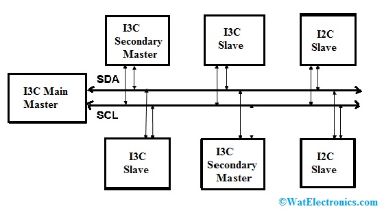
The I3C bus configuration is shown below which includes numerous devices like I3C Main Master, I3C secondary Master, I3C Slave & I2C Slave.

I3C Protocol Diagram
Main Master: It controls the I3C bus & its function.
Secondary Master: This takes temporary I3C bus control and it requires permission from the main master & passes control back toward the main master when control tasks are exercised.
Slave: It reacts to either common otherwise individual command of the I3C master.
Many I3C devices have several features which are suitable for their function within the I3C bus. Based on the requirement of the I3C Bus system, some features are allowed for particular bus instantiation.
For every I3C device, these features can be described within the device characteristic register. Master gets the information from the characteristic register throughout the power IP condition of the I3C bus.
At the beginning stage, the main master shall allocate an exclusive dynamic address to each device on the bus. This address can form a priority ranking for device interrupts. In the I3C bus, any secondary master present shall be made alert for dynamic address &characteristic registers.
I3C-based electronic hardware design mainly involves designing I3C Master, Slave & I3C system designs. So the designs will provide different challenges under various conditions of the design cycle.
For reliable operations, design engineers require a tool to debug the I3C device. So some of the main requirements are;
Design engineers who have developed master/slave, require completely working Master/Slave devices where they can arrange & test their designs. Check that the I2C device can co-exist with the I3C bus. The engineers require a tool to capture the communication between Master & slave to examine the traffic in the I3C protocol. A tool is required for capturing protocol traffic at a specific event. These events can estimate protocol activity or error conditions. Follow the I3C bus with the designed Master/Slave device within the I3C network.
I3C Protocol Message Format
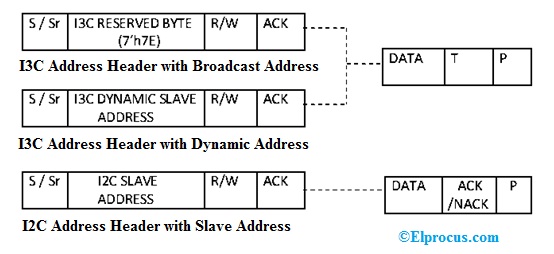
We know that the I3C protocol is a 2-wire bidirectional serial bus, which includes the SDA data line & SCL clock line. In SDR mode, the data transfer can be done up to 12.5Mbps including 12.5 MHz CLK frequency. The transaction of the I3C bus starts with the START condition. Here, SCL must be held high & SDA must go from high to low, following that the slave device address or broadcasted address through R/W bit must be sent.

I3C Message Format
After the first start address, arbitration may occur within the I3C bus, the device with a small address value would win. For broadcast address, all the slave devices over the I3C bus must send acknowledgment apart from I2C slaves. For slave address, simply particular slave transmits acknowledgment. Once the ACK ,I3C bus continues with write, read otherwise CCC command data is transferred then the I3C master can decide to STOP. Here, SCL should be held high & SDA must go from low to high otherwise can provide a repeated start after a transaction with the host controller command.
ACK – Acknowledge (SDA Low).
NACK – Not Acknowledge.
S – Start Condition.
Sr – Repeated Start Condition.
P- Stop Condition.
T – Transition bit Alternative to ACK or NACK.
PAR – Parity Bit.
I3C Protocol Vs I2C
The difference between the I3C protocol and I2C includes the following.
| I3C Protocol | I2C Protocol |
| I3C stands for the improved inter-integrated circuit. | I2C stands for an inter-integrated circuit. |
| This protocol is also called MIPI I3C & SenseWire. | This protocol is also called the 2-wire interface. |
| I3C protocol is high speed & power efficient. | As compared to I3c, it is not power-efficient and high speed. |
| In the I3C protocol, the dynamic address is assigned by the I3C master to all the slaves there on the bus. | In the I2C protocol, all the operations will take place through a static address. |
| The maximum working frequency is 12.5 Mhz. | The maximum working frequency is 3.4 Mhz. |
| The typical I3C network support is up to 33Mbps.
|
The typical I2C network support is up to 1Mbps.
|
| The I3C is a MIPI standardized protocol used to overcome the limitations of I2C. | I2C is a bus interface connection protocol integrated into devices for serial communication. |
| The effective data bit rate is 33.3 Mbps at 12.5 MHz. | The effective data bit rate is 3 Mbps at 3.4 MHz. |
Specification
The I3C protocol specification mainly defines various responsibilities for every type of device which includes SDA arbitration managing, assignment of dynamic address, hot-join features, HDR master & slave capacity.
SDA Arbitration Managing
SDA arbitration resolves bus ownership once many devices are transmitting right away. I3C protocol uses the SDA line throughout the arbitration procedure to follow the common open-drain approach. So the master normally manages the arbitration of SDA.
Dynamic Address Assignment
The main master of I3C allocates every device a single address, either once the bus is initialized otherwise whenever a new device is associated with an I3C bus.
Hot-join Feature
Once the I3C bus is activated then slaves don’t have to be turned on but it could be connected otherwise added later on. Activating such slaves is called a hot-join which allows the master to allocate a dynamic address to the slave once it asks for one.
HDR Master & Slave Capacity
Masters and slaves support 16.84Mbit/s of high data rates & the above data rates can be simply defined as HDR master/slave capable.
I3C Tools Debugging
When working with the I3C protocol, it is significant to have the correct set of tools to make sure the I3C design is executed properly. The complex hardware timing problems can be debugged by using an oscilloscope & logic analyzer.
A logic analyzer is the best tool to debug while designing the I3C Bus. So this can assist you to recognize the level issues of the protocol packet. An oscilloscope is used when you want to measure the I3C Device timing parameters. So, the I3C protocol analyzer is very helpful to perform I3C packet sniffing.
I3C Protocol Analyzer
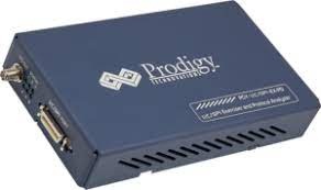
I3C Protocol Analyzer instrument like PGY-I3C-EX-PD mainly includes several features to capture as well as fix communication between host & design under test (DUT). I3C is an upcoming interface used for all sensor connectivity within mobile phones & automotive Industry.

I3C Network Analyzer
This can also be used for a less costly and reliable interface in embedded electronic applications for addressing the new data-intensive applications. The leading I3C protocol analyzer instrument like PGY-I3C-EX-PD allows the engineers to check the designs of the I3C protocol for its specifications by configuring the PGY-I3C-EX-ED device as master/slave, producing I3C traffic by error injection capacity & I3C Protocol decoding for decode packets.
The specifications of the PGY-I3C-EX-PD protocol analyzer include the following.
- It has the capacity to arrange it as Master or Slave.
- It has the capacity to configure LVR, DCR & BCR registers.
- It generates different I2C SDR, I3C & HDR Packets.
- It has the flexibility to upgrade the TSP unit &TSL encoding.
- Changeable I3C data speeds.
- Analysis of error in protocol decode.
- Simultaneously produce I3C traffic & protocol decode of the Bus.
- It has the capacity to write an exerciser script to merge several data frame generations at various data speeds.
- USB2 or USB3 host computer interface.
- Protocol activity listing view.
Applications
The applications of the I3C protocol include the following.
- The I3C interfaces are used as management buses within data centers.
- This protocol is used within the de-facto standard for incorporating different sensors within the system like gyroscopes, temperature sensors, etc.
Know more about I2S Protocol MCQs.
Thus, this is all about an overview of an I3C protocol that was mainly designed to make a single interface for mobile devices which can use many sensors. I3C provides a faster transmission rate through lower power consumption. So it is not only used for mobile devices but it can also be used for other embedded devices. For instance, wearable devices use many sensors in a restricted space & need low power consumption. Here is a question for you, what is the I2C protocol?