PLC Programming Concept
Programmable Logic Controllers (PLCs) are the major components in industrial automation and control systems. The controlling nature of PLC is ranging from simple- push button switching to a single motor to several complex control structures. The PLC programming is an important task of designing and implementing control application depending on customers need. A PLC program consists of a set of instructions either in textual or graphical form, which represents the logic to be implemented for specific industrial realtime applications.
A dedicated PLC programming software comes from a PLC hardware of specific manufacturer that allows entry and development of user application code, which can be finally download to the PLC hardware. This software also ensures Human Machine Interface (HMI) as a graphical representation of variables. Once this program gets downloaded to the PLC and if the PLC is placed in Run mode, then the PLC continuously works according to the program. Before going to the program of the PLC, let us know the basics of the PLC programming tutorial and its basic concepts.
PLC Programming Basics
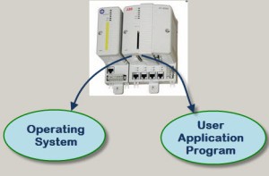
A CPU of the PLC executes two different programs:
1. The Operating System
2. The User Program
The Operating System
The operating system organizes all the functions, operations and sequences of the CPU that are not associated with a control task. The OS tasks include
- Handling a hot restart and warm restart
- Updating and outputting the process image tables of input and outputs
- Executing the user program
- Detecting and calling the interrupts
- Managing the memory areas
- Establishing communication with programmable devices
PLC programming Basics
The User Program
It is a combination of various functions which are required to process an automated task. This must be created by the users and need to be downloaded to the CPU of the PLC. Some of the tasks of the user program include:
- Initiating all the conditions for starting the specified task
- Reading and evaluating all binary and analog input signals
- Specifying output signals to all binary and analog output signals
- Executing interrupts and handling errors
In present industrial automation sector, there are several leading PLC manufactures that develop typical PLC’s ranging from small to high-end PLC’s. Each and every PLC manufacturer has its own dedicated software to program and configure the PLC hardware. But the PLC programming language is varied depending on the manufacturers. Some manufacturers have common programming languages and some others have dissimilar. Some of the standard programming languages of PLC are basically of two types, which are further sub-divided into several types, which are as follows:
1.Textual language
- Instructions List (IL)
- Structured Text (ST)
2. Graphical language
- Ladder Diagrams (LD)
- Function Block Diagram (FBD)
- Sequential Function Chart (SFC)
Compared with text based languages, graphical languages are preferred by many users to program a PLC due to their simple and convenient programming features. All the necessary functions and functional blocks are available in the standard library of each PLC software. These function blocks include timers, counters, strings, comparators, numeric, arithmetic, bit-shift, calling functions, and so on.
PLC Programming Devices
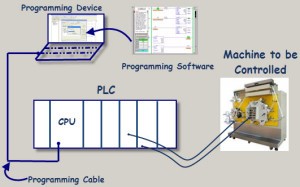
Various types of programming devices are used to enter, modify and troubleshoot a PLC program. These programming terminal devices include handheld and PC based devices. In the handheld programming device method, a proprietary device is connected to PLC through a connecting cable. This device consists of a set of keys that allows to enter, edit and dump the code into the PLC. These handheld devices consist of small display to make the instruction that has been programmed visible. These are compact and easy to use devices, but these handheld devices have limited capabilities.
PLC Programming Devices
Most popularly a Personal Computer (PC) is used for programming the PLC in conjunction with the software given by the manufacturer. By using this PC we can run the program in either online or offline mode, and can also edit, monitor, diagnose and troubleshoot the program of the PLC. The way of transferring the program to the PLC is shown in the above figure wherein the PC consists of program code corresponding to control application which is transferred to the PLC CPU via programming cable.
Ladder Logic PLC Programming
Ladder Logic PLC Programming
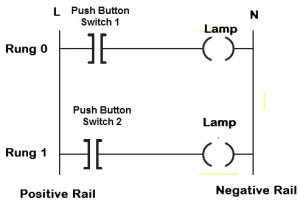
Among several programming languages ladder logic diagram is the most basic and simplest form of programming the PLC. Before going to program the PLC with this language, one should know some basic information about it. The below figure shows the hardwired-ladder diagram wherein the same lamp load is controlled by two push button switches, In case if any one of the switches gets closed, the lamp glows. Here two horizontal lines are called rungs which are connected between two vertical lines called rails. Each rung establishes the electrical continuity between positive (L) and negative rails (N) so that the current flows from the input to output devices. Some of the symbols used in ladder logic programming are shown in the figure.
Input switches are types include normally closed and normally opened as shown above. In addition to above given functional symbols, there are several functions like timer, counter, PID, etc., which are stored in the standard library to program complex tasks.
Step-By-Step Procedure for Programming PLC Using Ladder Logic
Step By Step Procedure for Programming PLC using Ladder Logic
The procedure for programming a PLC for a certain application depends on the type of standard manufacturer software tool and the type of control application. But in order to give a basic guidance to the students, this atrticle provides a simple approach of designing control application in PLC programming software, as given below But this way of programming doesn’t exactly fit into all the types of programming tools and control applications.
Step 1: Analyze and Get the Idea of Control Application
The primary step to program the PLC is to get the idea for which you are going to develop an application-based program. If you are driving a line follower robot by the use of DC motor when the push button is pressed. This status must be displayed by the LED light when the motor gets turn on. The motor is also attached with a sensor (Here it is considered as another switch) that detects obstacles, so when this turned on, the motor should be turned off. And correspondingly, if the motor switched off, the buzzer should be turned on.
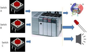
PLC Control Application
Step 2: List All the Conditions and Get the Design using Flowchart
The variables of the above project are M: Motor, A: Input Switch 1, B: Input Switch 2, L:LED and Bu: Buzzer, and the designing of the logic is easy with the implementation of flow chart, which is given below for the above application.
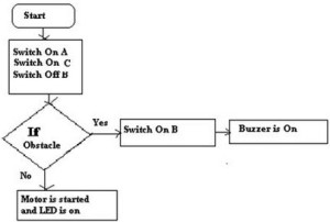
Flowchart of PLC Programming
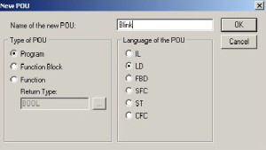
Step3: Open and Configure the PLC Programming Software
Open the programming software installed in the PC that comes with PLC hardware. Select the hardware model of the PLC in the software and configure it with appropriate input and output modules. Select the ladder language (LD) from the list of the programming languages, and choose the hardware processor and give a name for the program.
PLC Programming Software
Step 4: Add the Required Rungs and Address Them
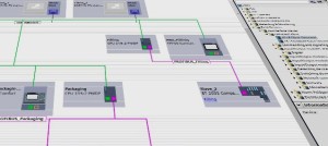
Add the required rungs based on the control application logic and give the address to the each and every input and outputs. The ladder logic diagram of the above discussed example is given below.
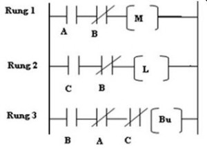
Example of Ladder Logic Program
Step 5: Check the Errors and Simulate It
Locate the Online section in the menu bar and select Online. Check for the errors and make necessary changes after selecting Offline. Again, go online and select the Run option to simulate it.
Step6: Download the Program to PLC CPU Memory
After the successful simulation of the program, download the program to CPU by selecting the Download option through a network or communication cable.
Please refer to this link to learn more about PLC Programming Languages.
Please refer to this link to know more about Programming Languages & its types, Allen Bradley PLC.
Please refer to this link to know more about PID Controller MCQs, PLC MCQs, Ladder Logic MCQs.
This is about the PLC programming basics and its procedural steps. We hope that the given content is clear and easy for understanding. It is also possible to know and understand it better with specified software of particular PLC like RSLogix 500, Codesys, step 7, etc. You can share your views, suggestions on PLC programming or if you want any help pertaining to the examples , then write to us in the comment section below.
Photo Credits:
- Procedure for Programming PLC by siemens