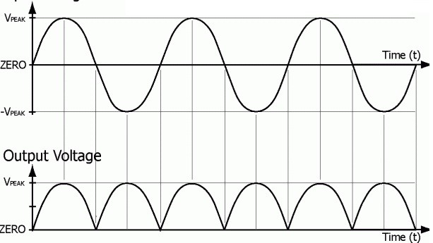
The purpose of the rectifier is to convert alternating current (AC) to direct current (DC). As in the half-wave rectifier, the rectifier output DC consists of AC components or ripples in it. To overcome this filter can be connected across the load so that the ripples can be reduced but this kind of circuitry is suitable for low power required applications. To overcome the problem of the half-wave rectifier, the model of the full-wave rectifier circuit is developed. In full-wave rectifier, full cycles of the supply are considered. The output of this circuit compared to half-wave rectifier consists of fewer ripples.
What is a Full Wave Rectifier?
A rectifier that utilizes both the positive and the negative half of the input cycle and undergoes rectification is defined as a full-wave rectifier. The average value of the output is higher in the full-wave rectifier compare to that of a half-wave rectifier. The numbers of ripples in the full-wave rectifier circuit are less in number producing the smoothest output.
Full Wave Rectifier Theory
In a full-wave rectifier, the two cycles of the supply input are rectified. To implement this technique basic full-wave rectifier requires two diodes. Each diode is utilized during each cycle. When the positive cycle is applied one diode conducts and during a negative cycle, the other tends to conduct. In this way, rectification is possible for a full-wave rectifier. Because of both the cycle’s utilization, there is no loss in power. Hence in this way, the working of a full-wave rectifier is described.
Types of Full Wave Rectifier
The full-wave rectifier can be designed by using with a minimum of two basic diodes or it can use four diodes based on the topology suggested. As we all know the basic principle of the diode it can conduct the flow of current in one single direction and the other is blocked. Using this concept as the basis many rectifiers are designed. Based on this the full-wave rectifier can be classified into two types. They are
(1) Center – Tapped
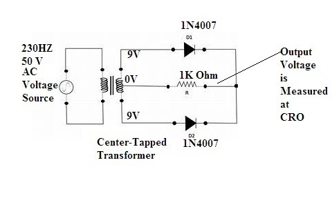
A center-tapped full-wave rectifier circuit consists of two diodes, a transformer, and a resistive load.
Full Wave Rectifier Circuit for Center – Tapped
A center-tapped transformer is a normal transformer that has a slight modification in it. Its secondary winding has a wire connected at the center. Hence the input supply AC voltage while passing through the secondary winding its voltage is divided into two halves. The one half is referred to positive half of the voltage. Whereas the remaining half of the voltage is for the negative part of the cycle.
The circuit consists of two diodes that are connected in parallel to each other along with the resistive load. The load is connected at the center-tapped wire of the secondary winding.
Full Wave Rectifier (Center- Tapped) working
The input is provided to the center-tapped transformer as it reaches the secondary winding the voltage is divided into two halves. During the positive half of the input cycles, the diode D1 is in forwarding bias condition indicating the conducting mode and the diode D2 is in the non-conducting mode because it is in reverse bias condition. The flow of current is observed at the terminal of diode D1.
During the negative half of the cycle, the diode D2 conducts because of the center-tapped transformer property and the diode D1 is in reverse bias condition that is in non-conduction mode. During this consequence the terminal at D2 one can find the flow of current through it and at D1 there is no evident flow of current or the current is blocked at D1 terminal.
During positive cycle diode D1 is in the range of conduction and when the negative cycle is provided the diode D2 will be in the conducting stage. Hence both the cycles are utilized here for rectification without any loss of input power. Hence we can say that the average output voltage of the half-wave rectifier is doubled compared to that of the half-wave rectifier.
(2) Full Wave Rectifier (Bridge)
A full-wave bridge rectifying circuit consists of four diodes connected in a diagonal manner that is nothing but in bridge topology. The functioning is very much similar like a center-tapped transformer. Even in this, both the positive side and the negative side of the cycles are utilized for rectification. The only difference is two more diodes in addition to the center-tapped are present here and there is no center-tapped transformer is used. Other than that remaining functionality is the same.
Full Wave Bridge Rectifier Circuit
As discussed earlier regarding the center-tapped transformer the bridge rectifier is also a type of full-wave rectifier. The four diodes connected in a bridge form. The technique used here is that the diagonally opposite diodes conduct during one half of the cycle and during the second half the remaining two diode conducts. Hence this basic model is simple to construct compare to that of any other rectifier circuit.
Working of Full Wave Bridge Rectifier
The diode A and C are diagonally opposite to each other whereas B and D are also connected in a diagonally opposite manner. During this the diodes A and C are in forwarding bias condition that is in conduction mode acts like closed switch then the path is established for the flow of current. Whereas diodes B and D are in reverse bias mode.
As the negative cycle of the supply reaches the bridge rectifying circuit diodes A and C becomes reverse bias and the diodes B and D act in forwarding bias mode. Hence the path is established for the flow of current between B and D. Where A and C diodes act like an open circuit and block the flow of current.
Full Wave Rectifier Experiment
Connect the circuit as per the circuit diagram is given. Provide it with the proper AC supply as per the given instructions. By using the CRO at the output side the voltage values can be measured. DC voltmeter ifs used to measure the load resistance value. Once the voltage and resistance values are calculated the other characteristics values can be calculated by simple substitution method in the respective equations.
Precision Full Wave Rectifier
It is a type of rectifier that consists of super diodes and mainly its configuration is based on operational amplifiers (opamps) so that its characteristics resemble ideal of the diode and also rectifier. During high precision signal processing, it is proven to be beneficial. In the normal rectifiers that have ordinary semiconductor devices as basic pieces of equipment can lead to the voltage drop. This can be overcome by using precision rectifiers.
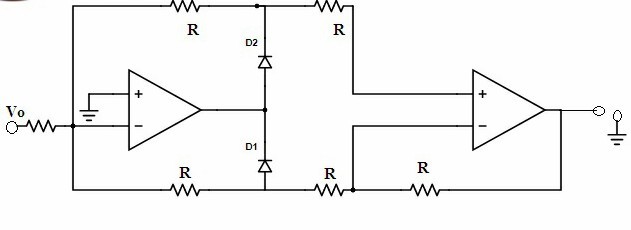
In the precision full-wave rectifiers, it considers both positive and the negative halves of the cycle. But either the output generated is completely inverted or non-inverted.
When the operation is performed on the precision rectifier the output generated as considered positive full-wave rectifier can be given as
Vo = |Vi|
The output generated for the negative full-wave rectifier can be given as
Vo = -|Vi|
Advantages
- The full-wave rectifier has more efficiency compared to that of a half-wave rectifier.
- There is the utilization of both the cycles. Hence there is no loss in the output power.
- As both the cycles used in rectification. There will be no loss in the input voltage signal.
- Ripple factor is less compared to that of the half-wave rectifier.
- Greater mean in DC value is achieved.
- Compare to the center-tapped full-wave rectifier bridge rectifier is cost-effective because the center-tapped is more costly.
Applications
- The amplitude for the modulating radio signal is detected using the full-wave bridge rectifier circuit.
- In electric wielding to supply steady DC voltage in a polarized way, this circuit is preferred.
- As the efficiency of rectification is high in this rectifier circuit, it is used in various appliances as a part of the power supply unit.
- It has the capability of converting high AC voltage to low DC value.
- In case of powering up of the devices like motors and LED devices these are used.
The above are some of the advantages and the applications of the full-wave rectifier circuit. It is used in various applications. These rectifiers are utilized more effectively compare to that of the half-wave rectifiers. The efficiency is high in these rectifiers and this is the main reason behind its wide usage in various application scenarios of power supply circuitry.
Full-wave rectifiers have more advantages compare to disadvantages in the power supply sector. The only disadvantage of this circuit is that the center-tapped transformer utilized here is costly. To overcome this disadvantage bridge rectifier circuit is constructed where the four diodes are connected in a bridge topology. Now can you just find out what is the basic difference between normal rectifiers and precision rectifiers?