In digital electronic projects, the encoder and decoder play an important role. It is used to convert the data from one form to another form. Generally, these are frequently used in the communication systems like telecommunication, networking, and transfer the data from one end to the other end. In the same way, it is also used in the digital domain for easy transmission of data, placed with the codes, and then transmitted. At the end of the receiver, the coded data are collected from the code and then processed to display. This article discusses what is encoder and encoder, working and their applications.
What are Encoder and Decoder?
The encoder is a device or a transducer or a circuit. The encoder will convert the information from one format to another format i.e like electrical signals to counters or a PLC. The feedback signal of the encoder will determine the position, count, speed, and direction. The control devices are used to send the command to a particular function.
Encoder
The decoder is a circuit used to change the code into a set of signals. The name its self tells the decoder because it has the reverse of encoding. The decoders are very simple to design.
Decoder
Working of Encoder
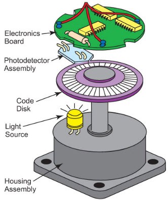
To create the signal in the encoders there are different types of technologies which include mechanical, magnetic, resistance, and optical is a most common. By using the interruption of light in the optical sensing the encoders will give feedback. The following diagram shows the basic structure of the incremental encoder by using optical technology.
Working of Encoder
The light emitted from the LED will pass through the disk code, which is with the opaque lines. If the encoder shaft starts rotating the light beam of the LED is interrupted by the opaque lines on the code disk. This will give the pulse signals and the light is present then is in ON state & if there is no light then the light is in the ON state. The signals are sent to the counters or controller and then send the signals to construct the desired function.
Truth Table of the Encoder
The decoders and encoders are designed with logic gates such as an OR-gate. There are different types of encoders and decoders like 4, 8, and 16 encoders and the truth table of encoders depends upon a particular encoder chosen by the user.
Simple Encoder
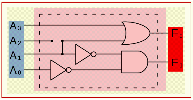
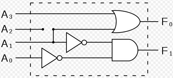
Here, a 4-bit encoder is being explained along with the truth table. The four-bit encoder allows only four inputs such as A0, A1, A2, A3 and generates the two outputs F0, F1, as shown below diagram.
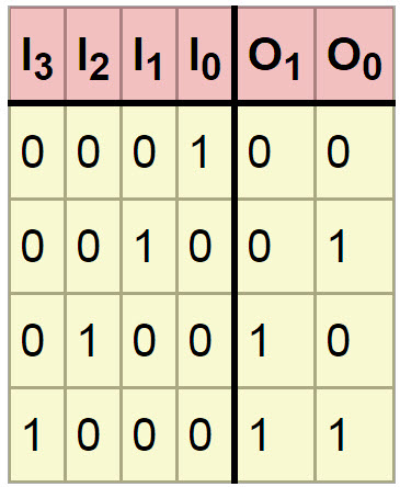
Encoder Truth Table
Types of Encoder and Decoder
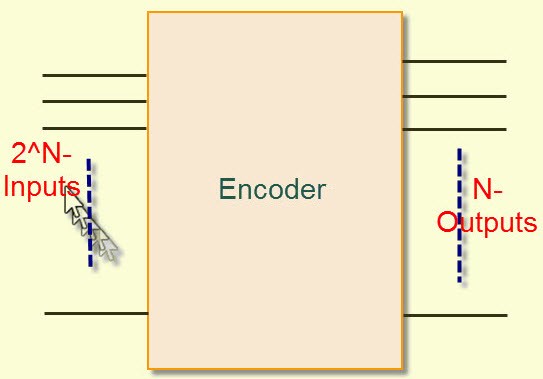
The encoder and decoder are used in many electronics projects to compress the multiple numbers of inputs into a smaller number of outputs. The encoder allows 2 power N inputs and generates an N-number of outputs. For example, in 4-2 encoders, if we give 4 inputs it produces only 2 outputs.
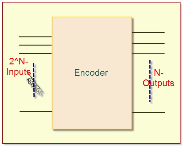
Encoder
Multiplexer
The multiplexers and demultiplexers are digital electronic devices that are used to control applications. A multiplexer is a device that allows multiple input signals and produces a single output signal. For example, sometimes we need to produce a single output from multiple input lines. Electronic multiplexers can be considered as multiple-input and single-output lines. In this case, the multiplexer used selects the input line to be sent to the output.
The digital code is applied to the selected inputs to generate the respective output. The digital code is applied to the selected inputs to generate respective output A common application of multiplexing occurs when several embedded system devices share a single transmission line or bus line while communicating with the device. Each device in succession has a brief time to send and receive the data. This is the special advantage of using this MUX.
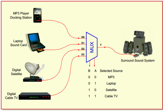
Multiplexer
Priority Encoder
The priority encoder is a circuit it compresses the multiple binary input to the small number of outputs. The output of the priority encoder is in the binary representation of the original number of most significant bits. Frequently there is a use of control interrupt request by acting the highest priority encoder. We can give at a time two or more than two inputs, then the highest priority takes precedence.
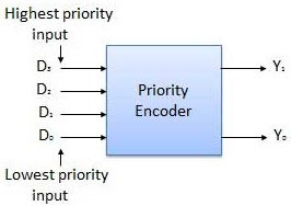
Priority Encoder
The example of the priority encoder is 4 to 2 encoder and the priority encoders are connected to the arrays to make large encoders. The highest priority encoders are at the left and X is an irrelevant value and the output V indicating that the input is valid or not. The large encoders in the priority encoders are 16 to 4 encoders, these are made with the six 4 to 2 encoders – for 4 to 2 encoders with the single source connected to their inputs and the remaining two encoders takes the output of the first four as input.
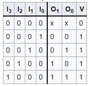
Truth Table of 4-to-2 Encoder
Logic Circuit of 2-to-4 Decoder
Introduction to Decoder
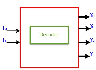
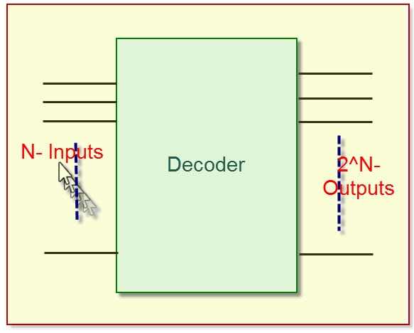
The decoder is an electronic device that is used to convert a digital signal to an analog signal. It allows a single input line and produces multiple output lines. The decoders are used in many communication projects that are used to communicate between two devices. The decoder allows N- inputs and generates 2 power N-numbers of outputs. For example, if we give 2 inputs that will produce 4 outputs by using 4 by 2 decoders.
Decoder
Truth Table of the Decoder
The encoders and decoders are designed with logic gates such as AND gates. There are different types of decoders like 4, 8, and 16 decoders and the truth table of decoder depends upon a particular decoder chosen by the user. The subsequent description is about a 4-bit decoder and its truth table.
Decoder Circuit
The four-bit decoder allows only four outputs such as A0, A1, A2, A3 and generates two outputs F0, F1, as shown in the below diagram.
Decoder Truth Table
Binary Decoder
In digital electronics, the binary decoder is a combinational logic circuit that converts the binary integer to the associated pattern of output bits. These are used in different applications like seven-segment display, memory address decoding. The function of the binary decoder is obtained if the given input combination has occurred.
Binary Decoder
3 to 8 Decoder
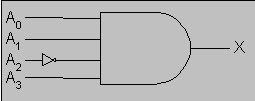
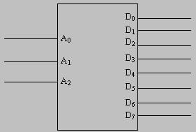
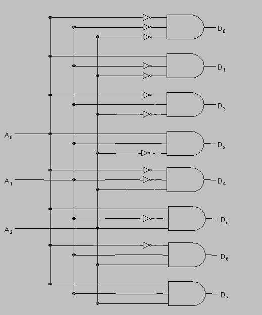
This type of decoder is called the 3 lines to 8 line decoder because they have 3 inputs and 8 outputs. To decode the combination of the three and eight, we required eight logical gates, and to design this type of decoder we have to consider that we required active high output.
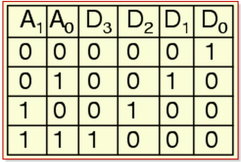
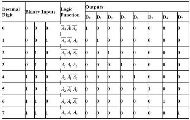
The below table shows the decoding of the 3 lines to 8 line decoder. To design this type of decoder we need active high output and for the given input combination the decoder output is one. The table shows an illustration of the decoding and also a logic symbol of 3 to 8 decoders.
3 to 8 Decoder
From the truth table of three-line inputs to eight-line outputs, we can show the logic circuit. The logic circuit consists of three NOT gates and eight NAND gates. Enable pin of NAND gates are connected together. The NOT gates can generate the complement of input and the NAND gates can produce the max in terms of each output.
Truth Tabl o 3-to-8-Decoder
Logic Circuit of 3-to-8 Decoder
2 to 4 Decoder
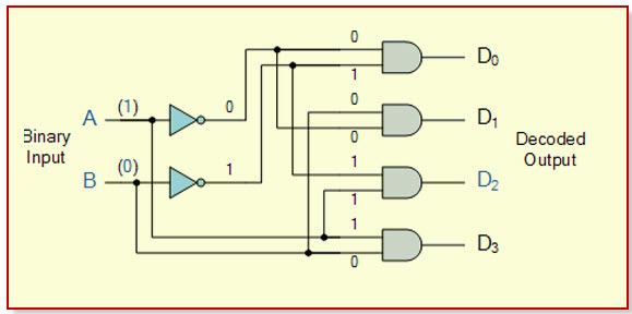
In the two to four decoders, the two input lines are decoded into four output lines. Therefore, this decoder consists of two input lines and four output lines. From the four output lines with only one output line will be active and the other three output lines are maintained at logic zero. The following diagram shows the two input lines to four output line decoders.
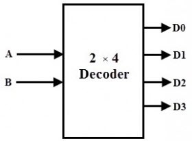
2 to 4 Decoder
The truth table of the two input lines to four output line decoders can be observed in the following. If the enable pins are active high, then for a given input the outputs from Y0 to Y3 are logic 1. When the two inputs are low, then the output of Y0 is logic 1 and the other outputs are logic 0.
If both the inputs are high, then the output of Y3 is logic 1 and the other output pins are logic 0. If the enable pin is zero then the output pins are logic 0. If the input pins A = 0 & B = 1 then the Y1 will be logic 1 or if the inputs A= 1 & B = 0 then the Y2 output pin will be logic 1.
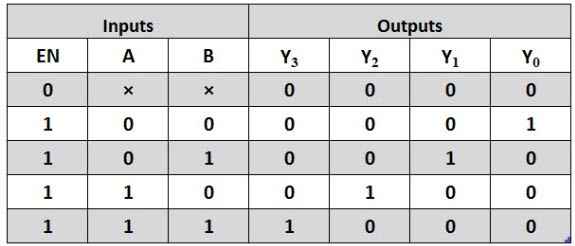
Truth Table of 2-to-4 Decoder
From the truth table the Boolean expressions of each output
Y0 = A ̅ B ̅
Y1 = A ̅ B
Y2 = A B ̅
Y3 = A B
By using the above equation, we can implement the logic circuit design of the two-line inputs of the four-line output. In this logic circuit, there are two NOT gates and four AND gates are used. The four enable pins are connected together and if the enable pin is zero, then all the outputs are zero.
If the enable pin is one, then the output depends on the product of the two inputs. In this, we have designed the logic circuit with the AND gate, but we can also implement it with the NAND gates by using the principle of minters.
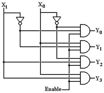
2-to-4 Decoder Logic Circuit
Decoder Design with NAND Gates
Some decoders are constructed with NAND rather than AND gates. In this case, all decoder outputs will be 1’s except the one corresponding to the input code which will be 0. 2-to-4 line decoder with an enable input constructed with NAND gates. The circuit operates with complemented outputs and enables input E’, which is also complemented to match the outputs of the decoder NAND gate.
The decoder is enabled when E’ is equal to zero. As represented by the truth table, only one output can be equal to zero at any given time, all other outputs being equal to one. The outputs represent the minterm selected by the inputs A1 and A0. The circuit is disabled when E’ is equal to one, regardless of the values of the other two inputs. If the circuit is disabled, then none of the outputs are equal to zero.
Please refer to this link to know more about Encoder and Decoder MCQs
Applications Of Encoder and Decoder
The applications of types of encoder and decoder include the following
- Speed synchronization of multiple motors in industries
- War field flying robot with a night vision flying camera
- A robotic vehicle with the metal detector
- RF-based home automation system
- Automatic health monitoring systems
1). Speed Synchronization of Multiple Motors in Industries
This system is used to synchronize motor speed by using RF technology. This project is applicable to many industries like steel plants, paper plants, and textile mills, where the motors are used to design simultaneously. All these motors used on conveyers are designed to be synchronized.
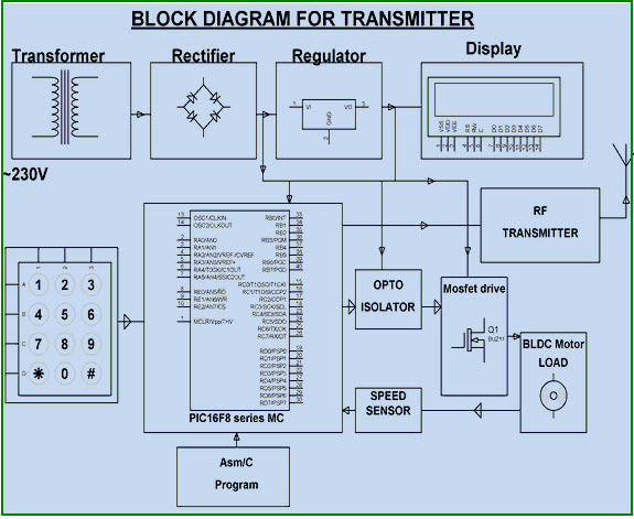
Speed Synchronization of Multiple Motors in Industries
In this system, one motor output is given as the reference speed for the other motors to follow the same speed. The proposed system consists of two blocks: transmitter and receiver blocks, which are built with an encoder and decoder.
A particular speed is sent by the transmitter with the help of the decoder. The receiver receives the data and converts the digital format to send the receiver system, and maintains the same speed as it has received. Thus, if a particular speed is set by the transmitter, then other motors run with the same speed by utilizing radio-frequency communication.
2). War- Field -Flying Robot with a Night Vision Flying Camera
This system with a wireless camera can wirelessly transmit a real-time video with night vision capabilities using RF technology, which is for remote operation. This kind of robot can be helpful for spying in War fields.
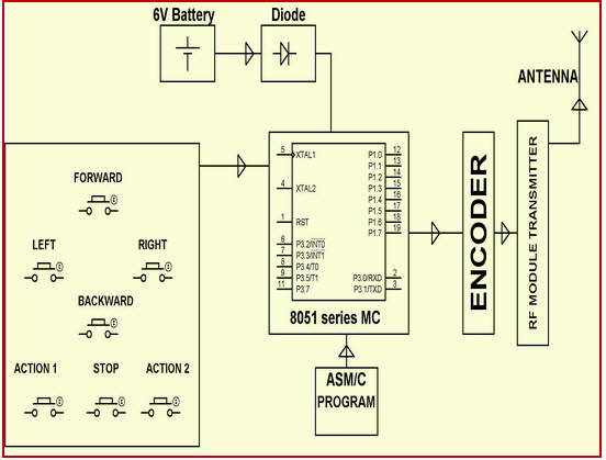
War Field Flying Robort with NJight Vision Flying Camera
In the transmitting end pushbuttons are used; commands are sent to the controller for controlling the movement of the robot either in forward, backward, left, right, directions.
The RF transmitter acts as an RF remote control that has the advantage of adequate range (up to 200 meters) with a proper antenna, while the receiver decodes before feeding it to another microcontroller to drive DC motors via motor driver IC for necessary work. A wireless camera is mounted on the robot body for spying purposes, even in complete darkness by using infrared lighting. The basic schematic diagram is shown above.
3). Robotic Vehicle with Metal Detector
The project is designed to develop a robotic vehicle that can sense metals ahead of it on its path similar to sensing land mines. The robot is controlled by a remote using RF technology. At the transmitting end, using push buttons, commands are sent to the receiver to control the movement of the robot either in forward, backward, and left or right directions. At the receiving end, two motors are interfaced to the microcontroller where they are used for the movement of the vehicle.
The RF transmitter acts as an RF remote control that has the advantage of adequate range (up to 200 meters) with a proper antenna, while the receiver decodes before feeding it to another microcontroller to drive DC motors via motor driver IC for necessary work.
Robotic Vehicle with Metal Detector
The RF transmitter acts as an RF remote control that has the advantage of adequate range (up to 200 meters) with a proper antenna, while the receiver decodes before feeding it to another microcontroller to drive DC motors via motor driver IC for necessary work.
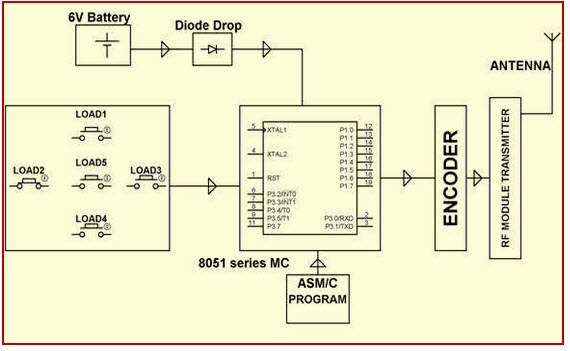
4). RF-based Home Automation System
The main goal of this project is to develop a home automation system with an RF- controlled remote. As technology is advancing so houses are also getting smarter. Modern houses are gradually shifting from conventional switches to a centralized control system, involving RF-controlled switches.
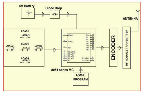
RF-based Home Automation System
Presently, conventional wall switches located in different parts of the house make it difficult for the user to approach them for operations. Furthermore, it becomes more & more difficult for the elderly or physically handicapped people to do so. Remote controlled home automation system provides a simpler solution with RF technology.
5). Automatic Wireless Health Monitoring System in Hospitals for Patients
In this project, a wireless communication system is designed and developed for remote patient monitoring. The primary function of this system is to monitor the temperature of a patient’s body and display the same to the doctor through RF communication. It is a very tedious method.
In this proposed system, a transmitting module continuously reads the patient’s body temperature through a digital temperature sensor; displays it on the LCD screen, and sends it to the microcontroller, which then transmits the encoded serial data over the air by RF (radio frequency) through an RF module.
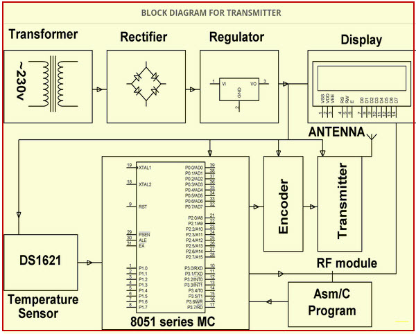
Automatic Wireless Health Monitoring System in Hospitals for Patients Block Diagram
6). Secret Code Enabled Secure Communication using RF Technology
The project is designed to send secure messages by using a secret code from a computer keyboard connected to the transmitting unit via RF technology. The message is retrieved at the receiver end only upon entering the secret code used by the transmitter. Thus, complete secrecy is maintained in this communication process. This project has a unique feature of tagging the message with a secret code as selected by the sender.
The message is then transmitted through the RF transmitting module. At the receiver end, the signal is received by the RF receiver module. The message is then retrieved only if the secret code is known to the receiving personnel. In this project, the encoders and decoders are used to transmit and receive the information. Once the secret code is entered, the message is displayed on the receiving unit on the LCD display.
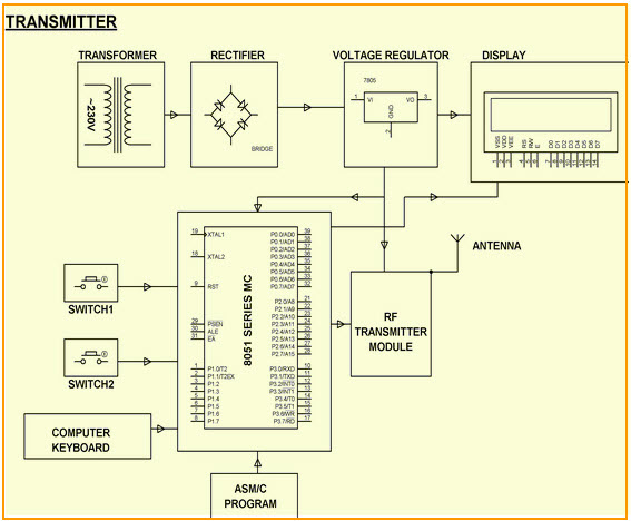
Secret Code Enabled Secure Communication using RF Technology Block Diagram
This is all about encoder and decoder, types of encoder and decoder, and their applications in communication-based projects. We believe that you might have got a better idea about the encoder and decoder concept, furthermore, any doubts regarding this article please give your valuable suggestions by commenting in the comment section below. Here is the question for you, what are the advantages of an encoder and decoder?