RC coupled amplifier is a basic type of amplifier with the various stages present in it. In other words, if we describe RC coupled amplifier we can say that an amplifier that consists of resistors and capacitors which acts a voltage divides and couplers to form multiple/single stage for better amplification. These are the basic circuits that are present in the various types of electronic equipment especially in RF signal or other communication devices as it helps in improving the signal strength through amplification.
What is an RC Coupled Amplifier?
An amplifier with the multiple stages based on the necessary levels of amplification can be defined as an RC coupled amplifier. It can be connected in any transistor configurations based on the efficiency of the system. It is widely used in audio and video communication devices.
RC Coupled Amplifier Circuit Diagram
The RC coupled Amplifier circuit may consists of various types of transistor configurations connected with the resistors and the capacitors. The configurations can be of the common emitter, common collector or the common base. In this article, we are discussing a single stage and two stages RC coupled amplifiers.
Single Stage RC Coupled Amplifier
Single-stage RC coupled amplifier can be termed as a preamplification circuit. Because these circuits are designed to improve the strength of the weak signals for the further amplification process.
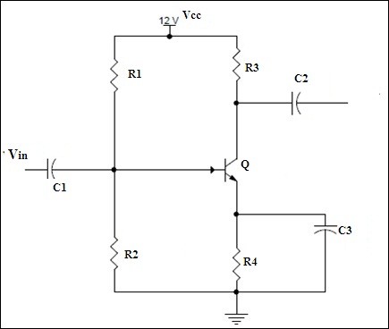
Single Stage RC Coupled Amplifier
Working:
This type of amplifier in the single-stage consists of the resistors R1, R2 and the capacitor. Here the capacitor is utilized so that it can provide the smoothing effect to the signal. It is capable of preventing the DC signals to enter and allow the AC one’s. The resistors R1 and the R2 that is connected at the input side to see to that the proper biasing voltage reaches the transistor so that the amplification process starts.
Further, the resistors that are present at the emitter and the collector are responsible to maintain the voltage drop to a minimum of up to 50 percent. With the help of the capacitors that are present at the emitter and the collector to avoid negative feedback because the stability is a major concern. In this way, the single-stage amplifier acts as the pre-amplifier.
Two-Stage RC Coupled Amplifiers
When the gain in the circuit is the major concern in such cases multiple stages for the amplifiers are designed. The purpose of this design is that it can improve performance by increasing the factor of gain in the circuit. 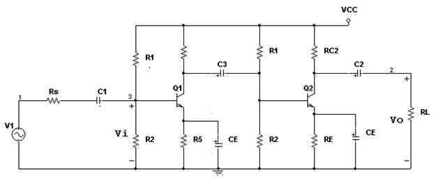
Two stage RC Coupled Amplifier
After the processing of the signal in the first stage the output of the first stage, the amplifier is connected to the second stage as the input. This made possible with the coupling capacitor present at the output of the first stage of the amplifier. One can observe after processing occurs at the second stage the output signal obtained has the increased gain factor in it and it is in phase with the input signal. In this way, the two stages RC coupled amplifier works.
Frequency Response of RC Coupled Amplifier
Bandwidth can be considered to be the major factor during the amplification of the signals. This can even influence the gain factor. When the curve or the graph is plotted in between the values of the gain and the frequency of the amplifier the resultant curve obtained is known as the frequency response of that particular amplifier. The bandwidth is the difference between the high and low frequency in which the gain remains at its higher value. It could be seen in the below graph that at a lower frequency the gain is low because the reactance of the capacitor is low at lower frequency and similarly at higher frequency the capacitor CE acts a short cirucuit an so again the gain is low.
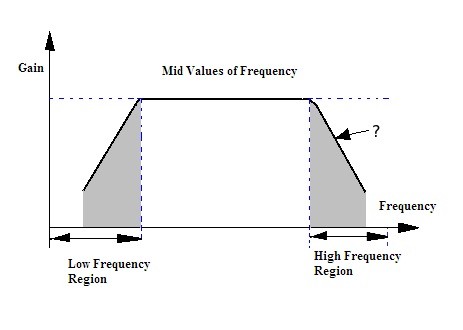
Frequency Response of the RC Coupled Amplifier
Experiment:
This experiment of the RC coupled amplifier can be performed with the basic resistors and the capacitors with the transistor circuit. So let us discuss the experiment in detail.
Aim: the purpose of the experiment is to obtain the frequency response and the gain of voltage for the RC coupled amplifier.
Apparatus Required:
The apparatus required for the experiment is as follows:
- Transistor (BC107) – 2
- Resistors (3.3K, 33K, 330 ohms, 1K) – 2
- Capacitors (100 micro F, 10 micro F) – 3 and 2
- CRO
- RPS
- Breadboard
Theory:
The experiment performed here is consists of a two-stage RC coupled amplifier. This is very efficient in terms of gain. The output of the first stage is coupled to the second stage as input through the capacitor. The capacitor is also known for blocking the DC signals and providing the smoothing effect to the signals obtained at the output.
As the gain obtained at the two stages will be different this gain values obtained are plotted on the curve with the frequency values. The final gain will be calculated with the product of the individual gains obtained at each stage. The curve obtained from this is known as the frequency response of the amplifier.
Procedure
- The input signal is applied with the function generator.
- The values of the voltage are observed and noted at the first stage and the second stage.
- Based on the values noted the gains at the individual stages are calculated.
- This is continued for multiple frequencies.
- Finally, the graph is plotted in between the gain values and the multiple frequencies applied to the circuit.
Observations
The observations of the output voltage & voltage gain for applied frequency can be done by using the above experiment and note down the values in the tabular form.
Precautions
- The type of transistor used and its terminals must be identified correctly for providing proper connection.
- The connections established must be tight.
Result
In this way, the gain value of the voltage and the frequency response of the RC coupled amplifier is calculated.
Applications of RC Coupled Amplifier
The applications of the RC coupled amplifier are as follows:
- Based on the frequency response of the RC coupled amplifier the gain remains constant to the maximum extent for the frequencies applied. Hence this makes this amplifier to be suitable for amplification of the audio signals.
- These amplifiers are preferred as Preamplifiers.
- This amplifier is also widely used in the amplification of the voltage signals.
In this way the these are proven to be very advantageous because of its low cost and the frequency response obtained. The presence of the components called resistor and the capacitors in this circuit makes it of low cost. This RC coupled amplifer can be made a multistaged one. For an even staged amplifier the output would be in phase with the input but for a odd stage amplifier like 3 or 5 the output would be in phase shift with the input. But as the circuit becomes older day by day it tends to get easily affected by the noise an so there would a loss in the quality of the signal. However, it is very advantageous in terms of the amplification of audio signals. But other than this can you tell what the major drawback of this amplifier is?