The purpose of the rectifier is to convert alternating current (AC) to direct current (DC) that is to undergo rectification. As the diode used in this process allows the flow of current in a unidirectional manner. Basing on this property of the diode the various types of rectifiers are designed. From the number of diodes used in the circuit the classification of rectifiers is done. Basically, the half-wave rectifier can be designed by using a single diode termed as single-phase rectifier. But if it is constructed using three diodes then it comes under the category of the three-phase rectifiers.
What is a Half Wave Rectifier?
A rectifier circuit in which the half part of the cycle either positive or negative of AC is converted to DC is defined as the half-wave rectifier. If the positive half cycle is considered then the negative half cycle of the source gets blocked or if the negative cycle of the source is considered in that case positive cycle gets blocked.
Working of a Half-Wave Rectifier
The circuit consists of a single diode in series with the AC supply and the load resistor. As the sufficient supply is provided the diode converts AC to DC the resultant will be unidirectional by utilizing the half cycle of the supply.
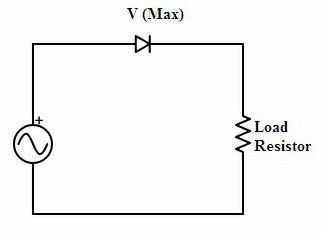
Half-wave rectification is carried out during the positive side of the supply. Because as per p-n junction diode concept it is evident that diode conducts during forwarding bias. But in reverse bias condition leakage current is generated due to which there is no possibility of conduction. In order to consider the operation for negative supply, the diode connected in the positive supply case must be changed its direction and reversely connected.
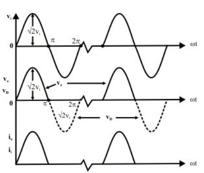
output waveforms of a half-wave rectifier
Half Wave Rectification for Positive Cycle Consideration
When the circuit is provided with a positive half cycle sufficient amount of voltage reaches the diode resulting it to function in forwarding bias condition. Hence the diode conduction takes place during forwarding bias. The process of rectification occurs at the load resistance where the generated voltage in the circuit is consumed by the load.
The property of the load resistor is to block the excess current produced in the circuit due to the diode or consume the unused current in the circuit. Based on the type of cycle used describes the type of rectifier. Here the positive side of the supply is considered so it is termed as a positive half-wave rectifier. In this way, the operation of half-wave rectifier for positive supply is considered.
Half-wave Rectification for Negative Cycle Consideration
The direction of the diode is changed in the circuitry. The remaining process is similar to that of diode conduction takes place during positive supply case. Now in this type of rectifier, the diode direction is changed so it begins to conduct during the applied negative supply of the voltage and the positive cycle gets blocked.
The current produced in the circuit gets measured at the load resistor. The output generated consists of all the negative pulses and there is no positive pulse present. Hence the operation of half-wave rectifier for the negative supply considered is discussed here.
The output generated in both the cases produces the rectified output but in the form of pulses. It means that due to half-wave rectification the output generated consists of pulsating Dc .but the intention of rectification is to produce constant DC.
Half Wave Rectifier with Capacitor Filter
In the above-generalized circuit of the half-wave rectifier, the output generated in the form of pulses. This pulsating DC is nowhere used or considered. In order to overcome this problem capacitor filter is introduced. The purpose of the filter is to convert the pulsating DC into its purest form.
As the output generated at the load resistor is time-varying. But coming to practicality one cannot prefer pulsating DC for any kind of electronic systems it requires DC in the purest form. The pulses formed are nothing but the ripples in the output. In order to make the DC in the pure form, the ripples must be suppressed. This is possible by connecting the capacitor or inductor filter across the load resistor.
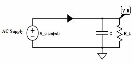
Here the capacitor filter is used for this purpose. The capacitor filter is connected across the load resistor and suppresses the ripples so that obtained output gets smoothened and the ripples are eliminated. In this, the output from pulsating DC is converted to its purest form in DC.
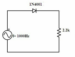
Half Wave Rectifier Experiment
- Consider the half-wave rectifier circuit with resistive load. Firstly take any four diodes and measure the threshold voltage value (V_T) using DMM.
- Once the threshold voltage is confirmed. Then the selected diode is connected in series with the supply voltage and the resistive load.
- The circuit is powered ON.
- The RMS and the average of the output voltage are measured.
- In this way, the output DC voltage is measured for the circuit and its characteristics can be calculated by using the formula.
Characteristics of Half Wave Rectifier
Some of the characteristics of the half-wave rectifier are as follows
RMS Value of a Half-Wave Rectifier
RMS is defined as the root mean square value. For load current, the RMS value can be given as
IRMS = Im/2
The RMS value of the output voltage is given as
VRMS = IRMS RL
On substituting the value of I_RMS from the above equation the equation for RMS voltage can be rewritten as
VRMS = Im/2 * RL
Form Factor of a Half-Wave Rectifier
The ratio of the RMS value to the DC value is defined as the form factor of that rectifier.
Form Factor=(RMS Value)/(DC Value)
Upon general calculation, the value of the form factor is 1.57.
The efficiency of a Half-Wave Rectifier
The efficiency of the rectifier is the ratio between the generated output power to the applied input power.
E = Pdc / Pac
The maximum efficiency produced is 40.6%.
Ripple Factor of a Half-Wave Rectifier
The output produced consists of pulsating DC rather than constant DC. These pulses in the output referred to as ripples. The number of ripples present at the output can be measured in terms of ripple factor. The symbol used for representing the ripple factor isγ.
If the value of the ripple factor is high it indicates that there are a number of ripples in the output DC of the rectifier. If it is low it indicated that less number of ripples present in the output DC of the rectifier.
Ripple Factor=(presence of AC component in the output voltage and its RMS value)/( DC component present in the output voltage )
It is also defined as
Ripple Factor=(Ripple voltage at the output)/( dc output voltage )
The ripple factor for half-wave rectifier is given as
γ=√((Vrms/VDC )2 -1)
The ripple factor value is 1.21. If the percentage is considered then it is 121% indicating that it has the highest ripple factor value. So this type of rectifier is not considered for practical applications.
The design of a half-wave rectifier is simple and cheap at the same time. Other than this output consists of ripples and practical implementation of this kind of circuit is highly impossible. Hence this rectifier has many disadvantages compared to that of advantages.
Advantages
- Requirements list of the components is less.
- The cost for the construction is low.
- Less number of components presence results in the construction of rectifier in the easiest manner.
- It is simple to analyze because the designed circuit is straight forward.
Disadvantages
- The output generated in this rectifier is in the form of pulses. It indicates the presence of ripples in the circuit.
- The ripple factor is high.
- During rectification, it considers either the positive cycle of the supply or negative cycle of the supply. However, in both the cases one cycle is ignored resulting in the power loss of the circuit.
- The voltage produced at the output is low.
- The transformer utilization factor (TUF) of the half-wave rectifier is low.
- Here the output generated requires the filter to be connected across the load because of the ripples generated at the output voltage.
- The above discussed are some of the advantages and disadvantages of the half-wave rectifier.
Applications
- The requirement of generating dc output voltage paves the way for the application of the half-wave rectifier circuit with the filter attached across the load.
- In the power supplies circuitry where the constant DC at the output is not considered as the major requirement at that case, the half-wave rectifier can be used.
Some of the basic advantages, disadvantages, and applications of the half-wave rectifier are discussed above. The basic idea of the half-wave rectifier and its characteristics are analyzed. As it has less efficiency it is not suitable for practical applications. As it is a type of rectifier why it is not considered for audio applications?