A current sensor is a significant component within various electronic and electrical systems which helps to ensure that devices and equipment operate efficiently and safely. So this current sensor measures the sum of electric current supplied throughout a conductor and generates a signal that is proportional to that current. Here, the output signal can be an analog voltage, digital output, or current. Thus, the generated signal can be used to show the measured current within an ammeter (or) further it can be stored in a data acquisition system for analysis, or used for controlling purposes. So the current sensor examples are; ACS71240, MAX471 IC, ACS71230, etc. This article elaborates on MAX471 IC, pinout, features, specifications, and applications.
What is MAX471 IC?
The MAX471 is a bidirectional, complete, and high-side current-sense amplifier used where power-line monitoring of battery or DC is important like telephones, portable PCs, etc. So, the MAX471 IC measures & monitors the charge and discharge of batteries & DC power lines. This IC has 35 milliohm current-sense resistors internally which measures up to 3A of current. Thus, it can also have a current output that can be changed into a ground-referred voltage.
Working
The MAX471 sensor IC uses a shunt resistor to measure current and amplifies the voltage drop across the shunt. This IC has a voltage measurement that ranges from 3V to 25 volts. So this IC utilizes a resistive voltage divider design to build the input voltage which is five times smaller. This IC has a 35-milliohm shunt resistor for measuring current supply up to 3A. So the current that needs to be measured can be transmitted throughout the shunt.
Further, MAX471 IC amplifies the voltage fall across the shunt and outputs it through the OUT pin. So the voltage at the OUT pin is always positive irrespective of the current direction. Thus, this output indicates the current flow direction which helps in monitoring the battery charging status.
MAX471 IC Pin Configuration:
MAX471 IC pin configuration is shown below. So this IC includes eight pins which are discussed below.
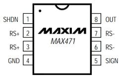
MAX471 Pin Configuration
- Pin-1 (SHDN): It is a shutdown pin of IC. This pin is pulled up high through a resistor to VIN to keep the IC enabled by default.
- Pin-2 & 3 (RS+): The RS+ of this sensor is connected to the load.
- Pin-4 (GND): It is a GND pin of the sensor IC.
- Pin-5 (SIGN): This is a digital pin of the sensor that indicates the current flow direction.
- Pin-6 & 7 (RS-): The RS- pin of this sensor is connected to the negative supply.
- Pin-8 (OUT): It is the output pin of the current sensor IC.
Features & Specifications:
The features and specifications of MAX471 IC include the following.
- The MAX471 IC measures both voltage and current so it makes perfect for quick power measurement.
- It is powered by the power source which is being measured.
- It operates from 3Volts to 36Volts.
- This IC includes an open-collector SIGN output that indicates the current flow direction to help the users monitor a battery condition.
- This IC outputs 1V for each amp measured.
- It has a 2% precision over temperature.
- This IC has a 3Amps sense capability with an in-built sense resistor.
- This IC can be connected through four pins to microcontrollers.
- Its voltage supply ranges from 4.5V to 36V
- Its sensing voltage ranges from 0V to +36V.
- The output voltage is proportional to 1V/A current.
- Its quiescent current is 100 µAmps.
- Accuracy is ±1.5% at full-scale
- Operating temperature ranges from -40°C to +85°Centigrade.
Equivalents & Alternatives:
Equivalent to MAX471 IC is ACS712 IC. So, alternative MAX471 ICs are; ACS71230, ACS37002, ACS711, ACS72981, ACS71240, ACS70331, ACS37002, etc.
Max471 Current Sensor Interfacing with Arduino
The Max471 current sensor interfacing with Arduino is shown below. So in this interfacing, you can easily learn how to utilize the Max741 IC with Arduino to measure the DC. Thus, the current value can be displayed on the serial monitor. After that, we need to connect the LCD to display the current value on the LCD.
Thus, the required components for this interfacing mainly include; Max471 current sensor IC, Arduino, LCD, load, and connecting wires.
The connections of this interfacing follow as
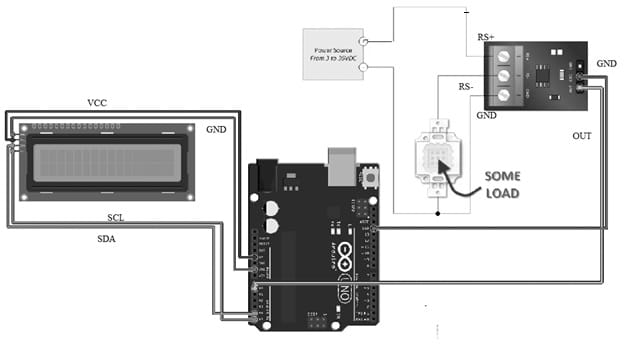
Max471 Current Sensor Interfacing with Arduino
- The positive terminal of the power supply connects to the RS+ pin of this IC.
- The high side of your load connects to the RS- pin of this IC.
- One GND pin of the IC connects to the other side of the load and the negative terminal of the power supply.
- The second GND pin of this IC connects to the GND pin of the Arduino.
- The OUT output pin of this IC connects to the A0 pin of the Arduino board.
Here’s the text revised to active voice:
- The connections of the LCD with Arduino are as follows:
- Connect the VCC pin of the LCD to the 5V pin of the Arduino.
- Connect the GND pin of the LCD to the GND pin of the Arduino.
- Connect the SDA pin of the LCD to the A4 pin of the Arduino.
- Connect the SCL pin of the LCD to the A5 pin of the Arduino.
Code:
The code for interfacing the Max471 current sensor with Arduino is shown below.
const int max471In = A0;
int RawValue= 0;
float Current = 0;
void setup(){
pinMode(max471In, INPUT);
Serial.begin(9600);
}
void loop(){
RawValue = analogRead(max471In);
Current = (RawValue * 5.0 )/ 1024.0; // scale the ADC
Serial.print(“Current = “); // shows the voltage measured
Serial.print(Current,3); //3 digits after decimal point
Serial.println(” amps DC”); //3 digits after decimal point
delay(200);
}
Thus, once the above code is uploaded then open the serial monitor at 9600 bauds. Thus, the result will be displayed on the serial monitor.
Code:
The LCD code for interfacing the Max471 current sensor with Arduino is shown below.
#include <Wire.h>
#include <LiquidCrystal_I2C.h>
// Set the LCD address to 0x27 or 0x3f for a 16 chars and 2 line display
LiquidCrystal_I2C lcd(0x27, 20, 4);
const int max471In = A0;
int RawValue= 0;
float Current = 0;
void setup(){
lcd.init();
lcd.backlight();
pinMode(max471In, INPUT);
Serial.begin(9600);
}
void loop(){
RawValue = analogRead(max471In);
Current = (RawValue * 5.0 )/ 1024.0; // scale the ADC
Serial.print(“Current = “); // shows the voltage measured
Serial.print(Current,3); //3 digits after decimal point
Serial.println(” amps DC”); //3 digits after decimal point
lcd.clear();
lcd.setCursor(0,0);
lcd.print(” Current: “);
lcd.setCursor(6,1);
lcd.print(Current);
delay(200);
}
So, once the connections are made by connecting an LCD then upload the above code. After that open the serial monitor at 9600 bauds and observe the results on the LCD screen.
Advantages & Disadvantages
The advantages of MAX471 IC include the following.
- The MAX471 IC utilizes <100 microamperes above a wide range of temperatures.
- This IC monitors battery currents without interfering with the ground lanes of the battery chargers.
- It has precise current measurements.
- This IC monitors both the charge & discharge of the battery.
- Its operational voltage ranges from 3V to 36V.
- It outputs 1 volt for each amp measured.
- This IC has 2% accuracy above temperature.
The disadvantages of MAX471 IC include the following.
- These sensors face difficulty while measuring large currents.
- These are sensitive to changes in temperature.
- They cannot be used with non-conductive materials.
- They can experience drift.
- They can fail at higher temperatures & currents.
- They generate heat, particularly at higher currents.
- Its response speed is slow.
- They can have complexity while achieving high accuracy.
MAX471 IC Applications
The applications of MAX471 IC include the following.
- MAX471 IC is used in power supplies to measure & regulate current supply to ensure secure and consistent operation
- This IC monitors and regulates the current supplied to motors to defend against overload conditions.
- It tracks & analyzes current utilization to optimize energy utilization.
- It is used in industrial automation to monitor & control current within machinery to assist with maintenance, process optimization & fault detection.
- This IC monitors the current supply within automotive electronics.
- This IC is used in IoT devices, battery chargers, portable devices, etc.
Please refer to this link for the MAX471 IC Datasheet.
Thus, this is an overview of MAX471 IC which is a complete, bidirectional, and high-side current-sense amplifier. So it is used in portable telephones, PCs, and other electrical systems wherever battery or DC power-line monitoring is significant. Thus, high-side power-line monitoring is especially useful in battery-powered systems since it does not interfere with the ground paths of the battery chargers or monitors often found in “smart” batteries. So, the MAX471 IC has an in-built 35mΩ current-sense resistor that measures up to ±3A battery currents. Here is a question for you, what is the ACS711 current sensor?